00198168-02_Technical_Training_TX-Series_EN.pdf - 第91页
5 Placement Heads 5.2 C&P20 P/M2 Head Technical Training SIPLACE TX-Series 10/2016 91 5.2.1.2 Technical Data* Description C&P20 P Component range 01005 to 2220, Melf, SOT,SOD: Camera type 23 0201 (metric) to 2220…
5 Placement Heads
5.2 C&P20 P/M2 Head
90 Technical Training SIPLACE TX-Series 10/2016
5.2 C&P20 P/M2 Head
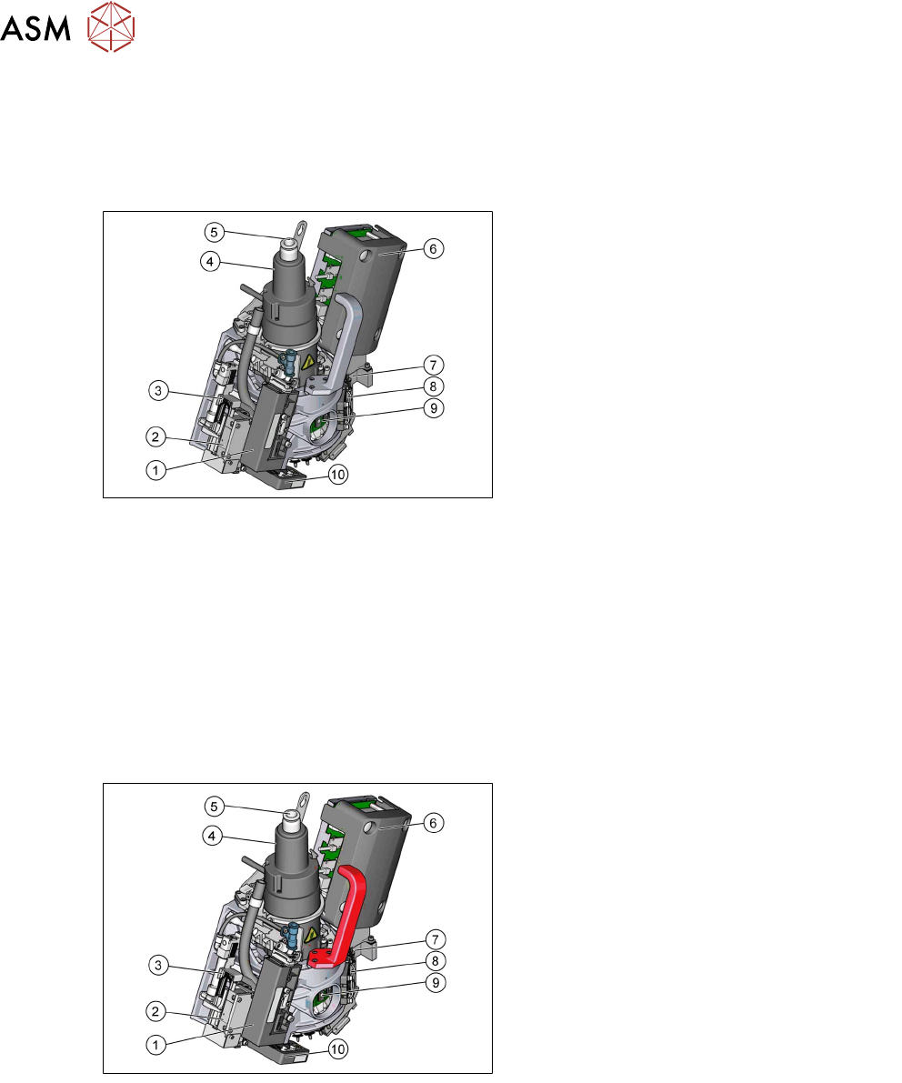
5.2.1 C&P20 P Head - Overview
5.2.1.1 Overview
1. Pressure control valve
2. Z Axis
3. Retract unit
4. Star motor
5. Air supply to holding circuit
6. Intermediate distributor
7. Component camera position
8. DP cooling Fan
9. DP control board
10. Component sensor
Features of C&P20 P Head
●
Can be used with pressurized air or vacuum pump (standard configuration).
●
Benchmark rate 39000cph.
●
Lower placement force at full speed.
●
Improvement of the usability and robustness.
●
Robust placement process of small components, C&P20 P head is fully capable to place
0201m.
●
Greater error tolerance during operation.
C&P20 M2 Head - Overview
1. Pressure control valve
2. Z Axis
3. Retract unit
4. Star motor
5. Air supply to holding circuit
6. Intermediate distributor
7. Component camera position
8. DP cooling fan
9. DP control board
10. Component sensor
C&P20 M2 differences
●
Optical the same but red handle
●
Star – resolution of the CP20M2 star is1000 digits / degree
●
DP –DPs controlled by C&P20 M2 firmware
●
Intermediate Distributor –C&P20 M2
●
Star, DP and Intermediate Distributor have own unique part numbers.

5 Placement Heads
5.2 C&P20 P/M2 Head
Technical Training SIPLACE TX-Series 10/2016 91
5.2.1.2 Technical Data*
Description C&P20 P
Component range 01005 to 2220, Melf, SOT,SOD: Camera type
23
0201 (metric) to 2220, Melf, SOT, SOD,
Bare-Die, Flip-Chip Camera type 41
Component height max 4.0 mm
Component weight max 1.0 g
Placement accuracy ± 30μm / 3σ Camera type 23
± 25 μm / 3σ Camera type 41
Angle accuracy ± 0.5° at 3σ
Programmable Placement force 1.3 - 4.5 N
Nozzle types 4xxx, (4235 calibration nozzle)
Nozzle changer NC Base structure CPx / Short
C&P20 M2 Head – Technical Data*
Description C&P20 M2
Component range 0201 (metric) to 2220, Melf, SOT, SOD,
Bare-Die, Flip-Chip Camera type 41
Component height max 4.0mm
Component weight max 1.0g
Placement accuracy with "high precision flag" ± 15μm / 3σ**
± 20μm / 3σ
Placement accuracy without "high precision
flag"
± 25μm / 3σ
Angle accuracy ± 0.3° / 3σ***
± 0.2° / 3σ****
Programmable Placement force 1.5 - 4.5 N
Nozzle types 4xxx, (4257 calibration nozzle)
Nozzle changer NC Base structure CPx / Short
* For full specification refer to the user manual.
**Only with SIPLACE TX2i micron 15μm accuracy class
***For SIPLACE TX micron with accuracy class 25μm
****For SIPLACE TX micron with accuracy class 20μm or SIPLACE TX2i micron 15μm
Machine Types
Machines X-Series S SX1 V2 SX2 V2 TX Series TX micron
C&P20 P X X X
C&P20 M2 X
Preconditions/ Requirement
●
TX Series: Station software ≥ SW709; SIPLACE Pro. ≥ 13
●
TX micron: Station software ≥ SW710.0; SIPLACE Pro. ≥ 14
Configuration
●
Vacuum pump operation (Standard).
●
Venturi System (Compressed air/ vacuum) operation (Option).
●
Component cameras:
– SST 23 (01005-2220 max. 6x6 mm/Visual field: 8.4 x 8.4 mm/Resolution: 17.1 µm/pixels)
– SST 41 (03015-2220 max. 6x6 mm/Visual field: 8.9 x 8.9 mm/Resolution: 10.1 µm/pixels)
●
Nozzle types 4xxx with corresponding magazines.
5 Placement Heads
5.2 C&P20 P/M2 Head
92 Technical Training SIPLACE TX-Series 10/2016
5.2.2 Main Parts/ Unit Overview
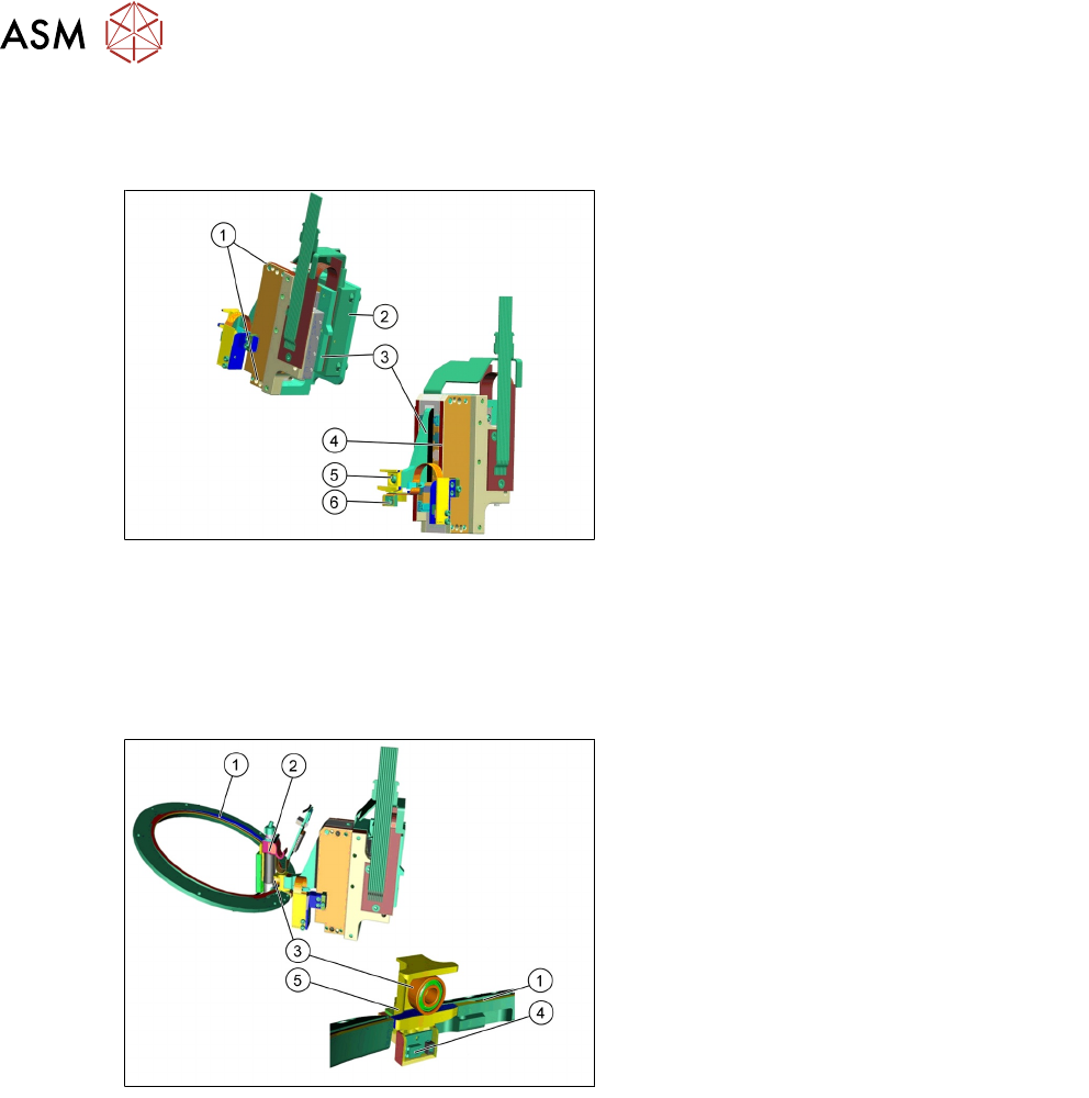
5.2.2.1 Z Axis Drive
1. Mounting for Z Axis
2. Incremental measurement system
3. Primary part of linear motor
4. Secondary part of linear motor
5. Ceramic jaw
6. Light barrier Z-down (analog)
●
The Z Axis is supplied with 40V/ 3,28A from the MHCU.
●
The incremental reader head has an EEprom on the connector to store statistic and axis data.
●
The Z Axis unit and the raceway are complementary parts, it is not possible to change one of
the above mentioned parts.
5.2.2.2 Z Axis
1. Raceway
2. Segment 1
3. DP ball bearing
4. Light barrier Z-down
●
The Z-drive is not a spare part!
●
The light barrier Z-down is not a spare
part!
5. Jaw
Functionality of the Z-drive
●
The ceramic jaw is mounted to the primary part of the Z Motor for mechanical docking of the
DP drives.
●
The analog Z-down sensor is located at the placement position for recognition of the Z Axis
set down position.
●
When the Z Axis springs into place, this sensor sends a signal to the axis controller card
(MHCU) The "light barrier down" signal is directly linked to the measurement signal of the
Z Axis incremental encoder.