00197195-02-UG SetupCenter 5.1_en.pdf - 第20页
Starting Setup Center The User Interface Display Area for Open Setups 20 User Guide SIPLACE Setup Center 5.1 Double arrow icon The double arr ow (1) icon marks those feeders which a re compatible with Random Setu p. This…
Starting Setup Center
Display Area for Open Setups The User Interface
User Guide SIPLACE Setup Center 5.1 19
2.2.2.4 Track Icons
The SIPLACE Setup Center user interface shows information about the feeders on the tracks.
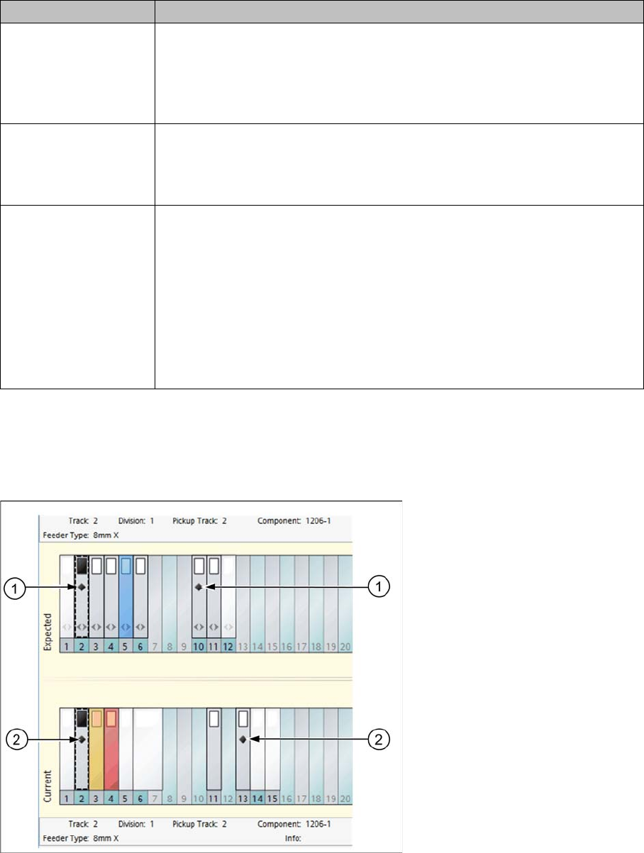
Diamond icon
The diamond icon marks those feeders with components in the expected setup (1) which also have
equivalent components (2) in the current setup. This gives you a clear view of the tracks in the current
setup on which this component is already configured. You can therefore see where this component can
still be configured or picked up, something which is particularly helpful for Random Setup. Select a track
in the expected setup and all tracks with equivalent components in the current setup will be marked with
the diamond icon.
Feeder - gray The feeder is on a track which is included in the target setup of the setup ver-
ification. This track has been verified successfully. When you have an active
component level indicator with thresholds, the component level will also be
above the warning threshold.
Example: track 2
Feeder - orange The feeder is on a track which is included in the target setup of the setup ver-
ification. This track has been verified successfully. The component level has
undershot the warning level of the component level indicator.
Example: track 3
Feeder - red ▪ The feeder is on a track which is included in the target setup of the setup
verification. This track has been verified successfully. The component lev-
el has undershot the stop level of the component level indicator.
▪ An incorrect feeder type is on a track which is included in the target setup
of the setup verification.
▪ The feeder is on a track which is included in the target setup of the setup
verification. The track has been locked by Setup Center or an external
system (padlock symbol).
Color Meaning
Starting Setup Center
The User Interface Display Area for Open Setups
20 User Guide SIPLACE Setup Center 5.1
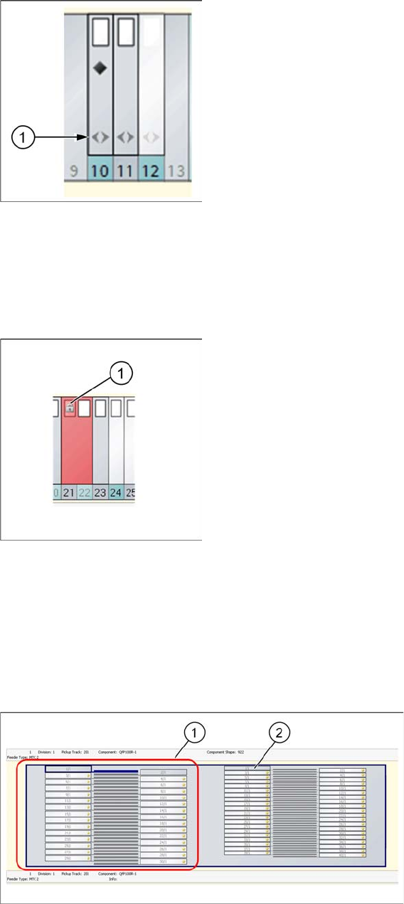
Double arrow icon
The double arrow (1) icon marks those feeders which are compatible with Random Setup. This means
those feeders in the setup which were sent to the line in Random Setup mode. This shows a clear over-
view of which feeders do not need to be configured on the exact track. Feeders which are not compatible
with Random Setup include S feeders, manual trays etc.
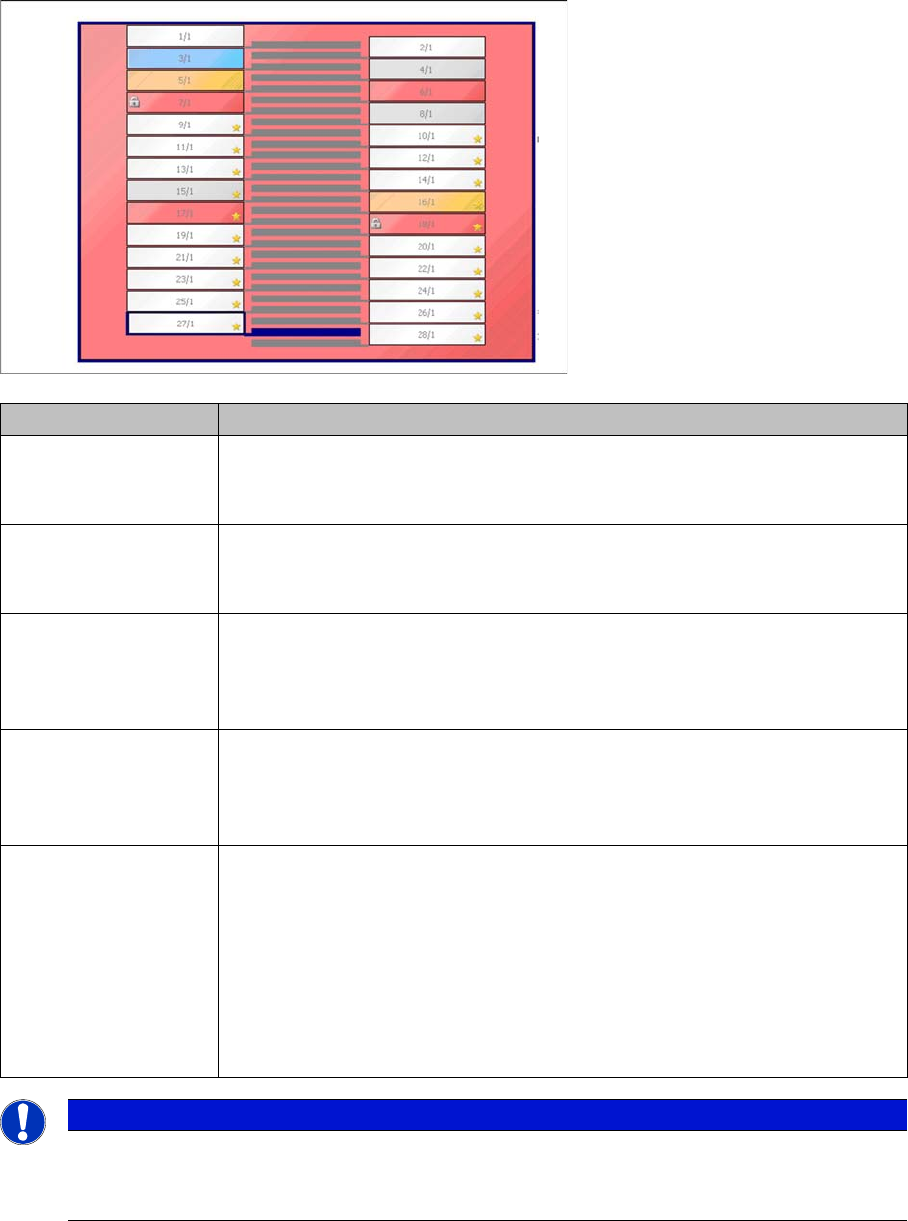
Padlock (gray) icon
A gray padlock (1) shows the following states:
▪ This feeder has been locked by Setup Center
▪ This feeder is locked by an external system.
▪ The splice monitor has reported an error for this feeder.
2.2.2.5 Location Display - Tray
The top half of your screen shows the display area for the selected location.
Legend
1. Tower
2. Level
Starting Setup Center
Display Area for Open Setups The User Interface
User Guide SIPLACE Setup Center 5.1 21
2.2.2.6 Color Coding of Levels
2.2.2.7 Line Display
The bottom half of the user interface shows the configured line with the active setup.
The machine state is shown by a range of different colors:
Blue: The tables and stations in use are marked blue.
White: The tables and stations which are empty or not in use are marked white.
Color Meaning
White The level is not subject to component verification. It does not matter whether
a component is configured or not in the level.
Example: level 1/1, 2/1, 9/1, 10/1, 11/1, 12/1, 13/1, 14/1, 19/1, to 28/1,
Blue The level is subject to component verification. This level has not yet been
checked successfully.
Example: level 3/1
Gray The level is subject to component verification. This level has been verified
successfully. When you have an active component level indicator with thresh-
olds, the component level will also be above the warning threshold.
Example: level 4/1 and 8/1
Orange The level is subject to component verification. This level has been verified
successfully. The component level has undershot the warning level of the
component level indicator.
Example: level 5/1
Red ▪ The level is subject to component verification. This level has been verified
successfully. The component level has undershot the stop level of the
component level indicator.
– Example: lane 6/1
▪ The level is subject to component verification. This level has not been ver-
ified successfully. The level has been frozen by Setup Center or an exter-
nal system (padlock symbol).
– Example: track 7/1
NOTICE
Levels with asterisk
Levels marked with an asterisk do not contain a component in the target setup. These levels
can be used as dynamic spare tracks.