00197195-02-UG SetupCenter 5.1_en.pdf - 第58页
Setting System Components Station Software Settings (from Version 60x) Component Level Indicator 58 User Guide SIPLACE Setup Center 5.1 Representation and Numbering of the Trays Legend 1. Tower 1 2. Tower 2 3. Selected C…
Setting System Components
Component Level Indicator Station Software Settings (from Version 60x)
User Guide SIPLACE Setup Center 5.1 57
Ticked: The threshold is the same for all tracks and will be taken into account.
Not ticked: The threshold will not be included in the calculation.
Multiple thresholds can be selected. These are then connected to one another with a logical "OR"rela-
tion.
If no thresholds have been entered, the track runs idle without a message being issued.
4.1.2.2 Menu Matrix Tray Changer (MTC)
The functions for the Matrix Tray Changer (MTC) can be started with the MTC switch in the toolbar with
which you want to work:
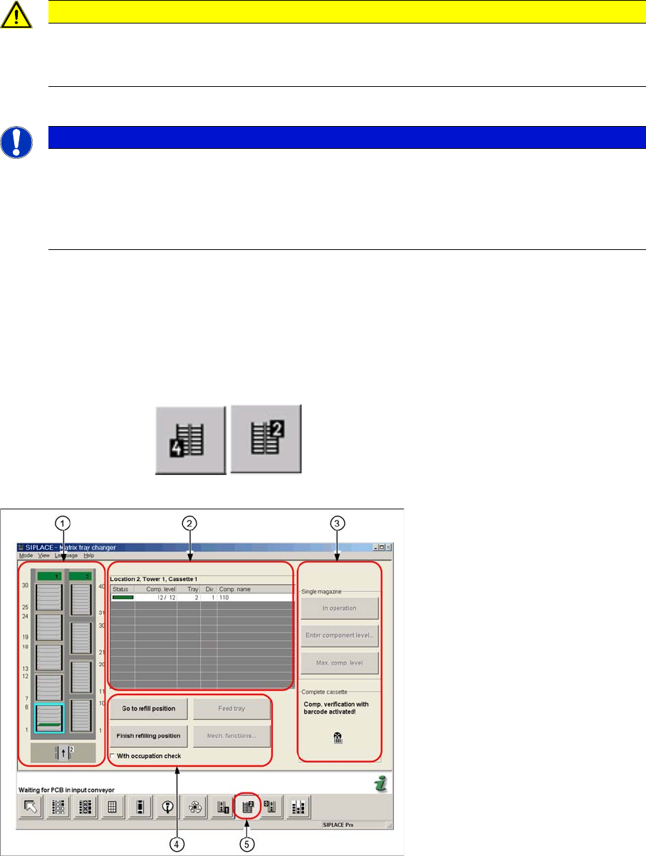
The figure below shows the component level indicator menu of the MTC.
Legend
1. Representation of the MTC in the user interface
2. Component level indicator view of all verified levels in a selected cassette
3. Switches and component level indicator view for a single magazine or a whole cassette.
4. Switch for refill position of magazines
5. Button for the component level indicator of the MTC
CAUTION
Component level indicator in combination with setup verification
The component level indicator in connection with setup verification should always be run with
activated stop thresholds.
NOTICE
Component level indicator can be deactivated for individual tracks
If you want to be able to disable the component level indicator for individual tracks, activate the
option "'Running tracks empty' is permitted" on the product CD for forced verification and the
component level indicator. This gives you the possibility of intentionally running individual tracks
empty.
Setting System Components
Station Software Settings (from Version 60x) Component Level Indicator
58 User Guide SIPLACE Setup Center 5.1
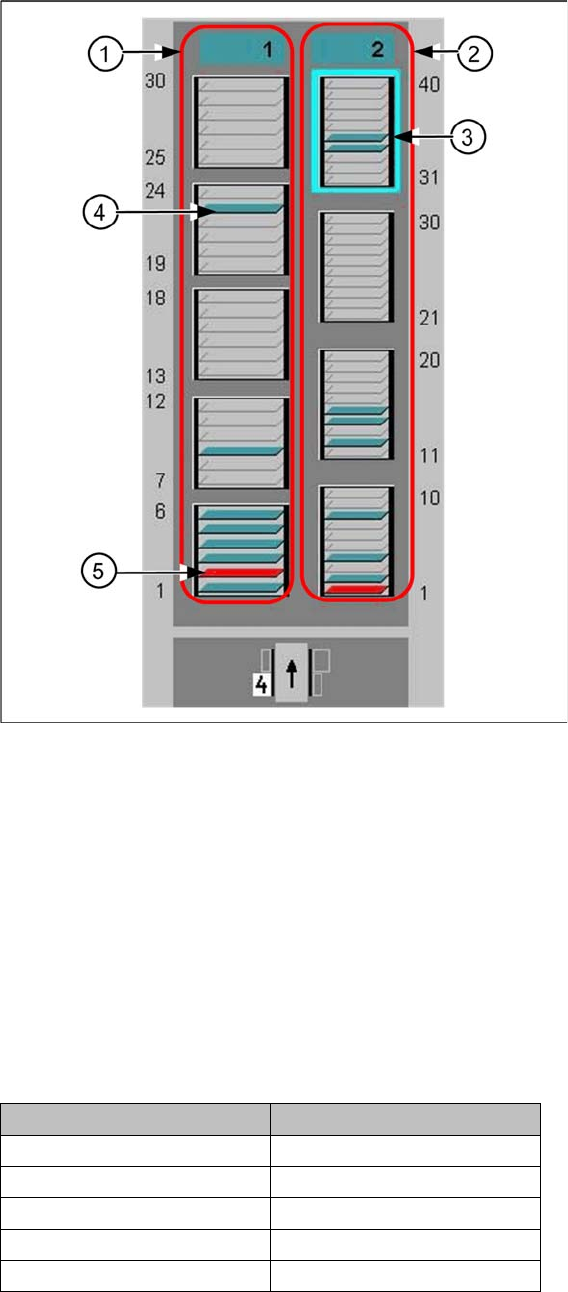
Representation and Numbering of the Trays
Legend
1. Tower 1
2. Tower 2
3. Selected Cassette
4. This tray is occupied
5. This tray is out of operation
Color coding of the tray symbol in the graphic:
▪ Gray: Tray is not available in the setup.
▪ Green: Tray is ready for operation.
▪ Red: Tray is out of operation
The trays are numbered as follows:
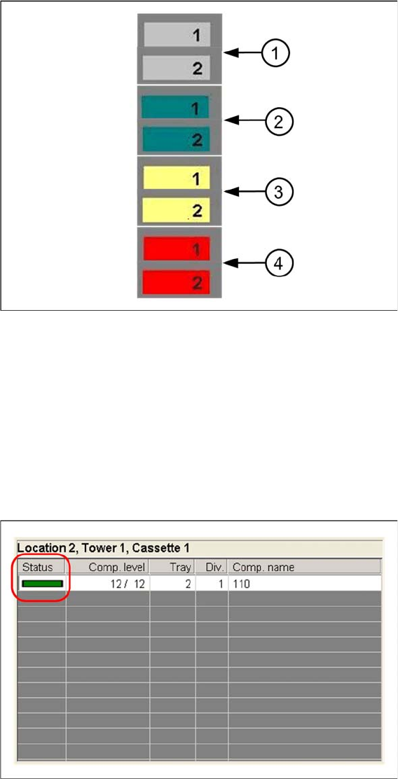
Color coding of the tower symbol in the graphic
Tower 1 Tower 2
Cassette 5: 25 - 30 --
Cassette 4: 19 - 24 Cassette 4: 31 - 40
Cassette 3: 13 - 18 Cassette 3: 21 - 30
Cassette 2: 7- 12 Cassette 2: 11 - 20
Cassette 1: 1 - 6 Cassette 1: 1 - 10
Setting System Components
Component Level Indicator Station Software Settings (from Version 60x)
User Guide SIPLACE Setup Center 5.1 59
Legend
1. Tower has not been referenced.
2. Tower is ready for operation.
3. Tower is in refill position
4. Tower is out of operation
Component Level Indicator View
The view provides information about component levels and the status of all the checked levels in a se-
lected cassette.