00193892-0402_AI_FeederCoverFlap_DE+EN.pdf - 第43页
Assembly instructions Feeder cover flap, SIPLACE HF-series / X-series / D3 05/2009 Edition 43 2.3.1 Assembly kit s 2 If there still the old empty tape duct with FS -03 is mounted, y o u need additionally: 2 2 2 2 2 Quant…
Assembly instructions Feeder cover flap, SIPLACE HF-series / X-series / D3
05/2009 Edition
42
2.3 Parts required
Feeder cover flap location 1 / 3: 00119933-xx 2
Feeder cover flap location 2 / 4: 00119910-xx 2
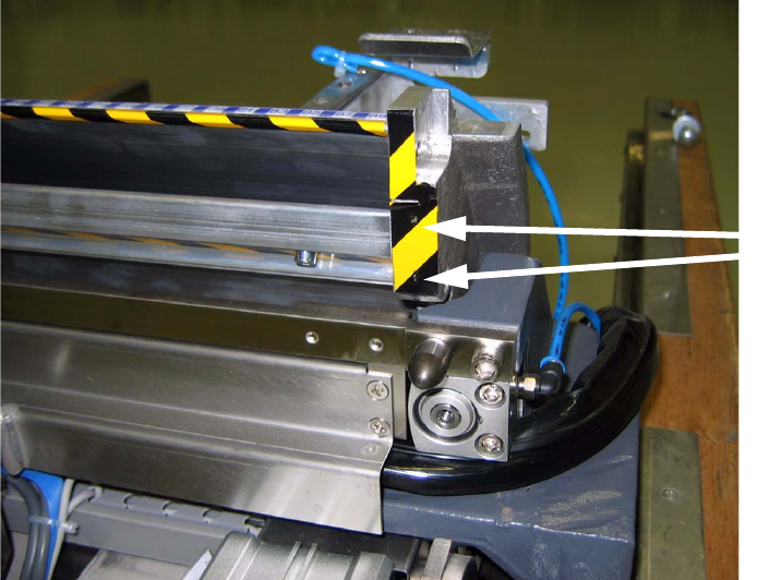
The empty tape duct must be replaced on machines fitted with empty tape duct 03021990-03
or older. Empty tape duct with revision -04 or higher must be used.
The reason for this replacement is that the ducts with revision -03 and older don’t have the
threaded holes required to attach the gas-pressured lifts. The following picture provides the
best explanation. 2
2
2
2
2
2
2
2
2
2
2
Threaded holes
are located
behind the
adhesive tape

Assembly instructions Feeder cover flap, SIPLACE HF-series / X-series / D3
05/2009 Edition
43
2.3.1 Assembly kits
2
If there still the old empty tape duct with FS -03 is mounted, you need additionally: 2
2
2
2
2 Quantity 2 Name 2 Item number 2
2 1 2 Feeder Cover HF Sec. 1/3 compl.: 00119933-xx 2 03065933-xx 2
2 1 2 Feeder Cover HF Sec. 1/3 2 03065992-xx 2
2 1 2 Flap Switch X-series 2 03056172-xx 2
2 1 2 Feeder Cover HF Sec. 2/4 compl.: 00119910-xx 2 03065932-xx 2
2 1 2 Feeder Cover HF Sec. 2/4 2 03065999-xx 2
2 1 2 Flap Switch X-series 2 03056172-xx 2
2 1 2 Empty tape duct 2 03021990-04 or higher 2

Assembly instructions Feeder cover flap, SIPLACE HF-series / X-series / D3
05/2009 Edition
44
2.4 Safety instructions
WARNING
The safety instructions from the “Operational safety” chapter of the user manual and servicing in-
structions take precedence over these instructions. 2
The SIPLACE placement machines are supplied with main power voltage.
Consequently parts of these systems carry dangerous voltages! This voltage is present at certain
modules inside the machine base, even when the machine is switched off at the main power
switch.
Incorrect handling of the placement machine or touching live parts of the machine can result in
death or severe injury, and considerable damage to equipment.
BEFORE starting any work, shut down the operating system correctly, then switch the machine
OFF at the main power switch and disconnect from the main power supply. In addition, the com-
pressed air supply must be switched off at the compressed air unit's main valve in the machine
base and vented by actuating the needle valve on the compressed air unit.
There is DANGER for heart pacemaker wearers in the vicinity of the linear motors, as described
in detail in the "Special safety instructions for working in the vicinity of strong magnetic fields"
section of the user manual and service manual.
Always follow the accident prevention regulations, DIN or other standards and special safety
rules applicable in your country.
Pay attention to the information concerning residual voltages in the Operational Safety chapter.
Follow the ESD regulations as described in the operational safety section of the operating
instructions.
During the retrofit, always secure the machine to prevent access by other people and to prevent
it being switched on again as described in the "Lock out and tag out procedure" in the user man-
ual.
Working with the SITEST program further increases the risk of accident.
The SITEST program must only be used by authorized and trained personnel.
2
2
2.4.1 Definitions
2
Please note 2
2
2
2
Caution 2