00193892-0402_AI_FeederCoverFlap_DE+EN.pdf - 第64页
Assembly instructions Feeder cover flap, SIPLACE HF-series / X-series / D3 05/2009 Edition 64 : Drill 1 hole with a 5 mm diameter metal drill bit. 2 : Place the counterbore in the drilled hole and thus drill a la rger ho…
Assembly instructions Feeder cover flap, SIPLACE HF-series / X-series / D3
05/2009 Edition
63
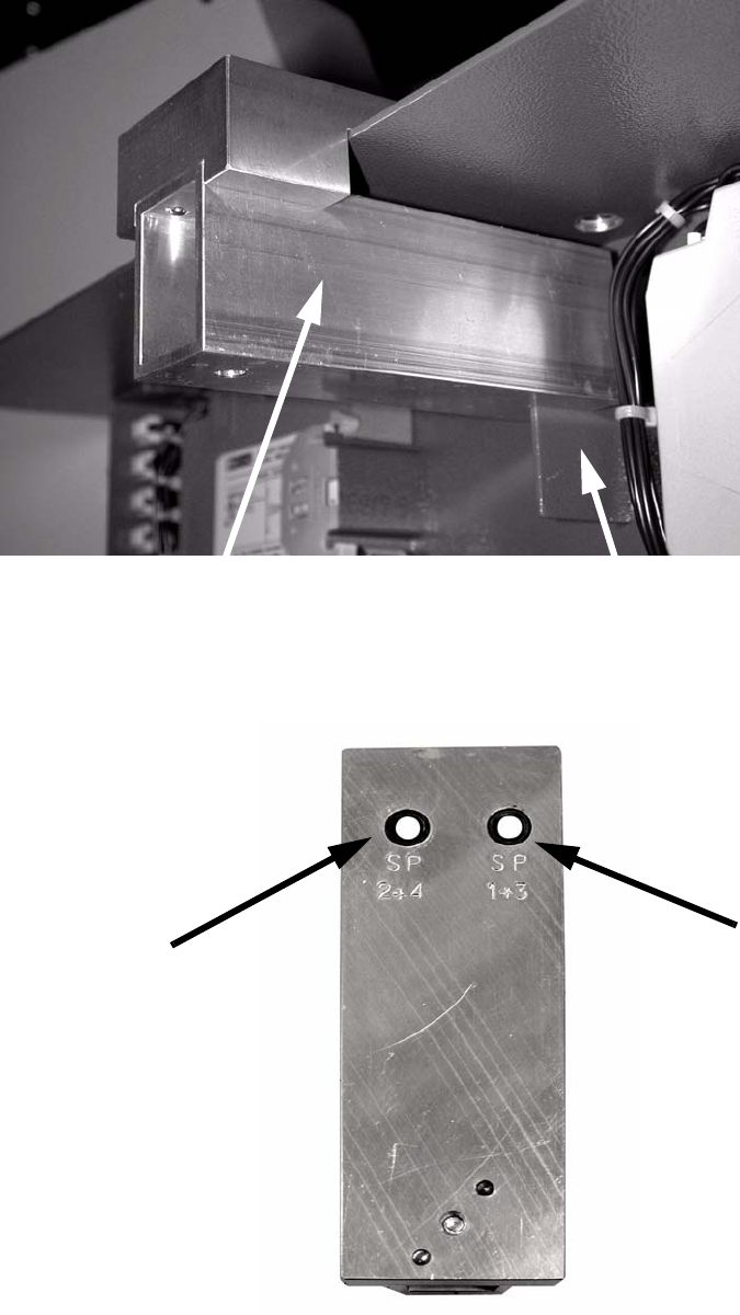
: Attach the drilling gauge as shown in the photograph.
2
The drilled hole must be selected to suit the location: 2
2
Drilling gauge (item no.: 03033936-01)
Partition in the side panel
Drill hole for
locations 1 and 3
Drill hole for
locations 2 and 4
Assembly instructions Feeder cover flap, SIPLACE HF-series / X-series / D3
05/2009 Edition
64
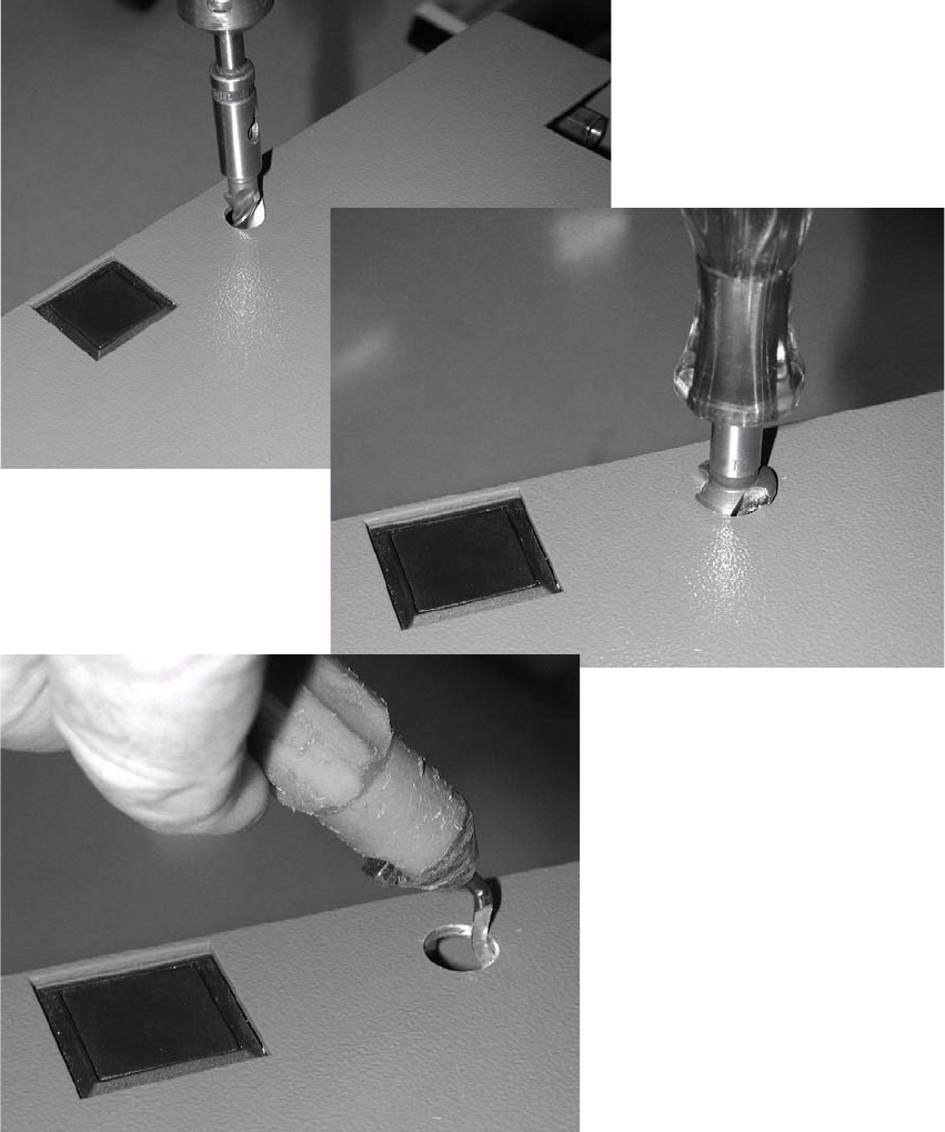
: Drill 1 hole with a 5 mm diameter metal drill bit.
2
: Place the counterbore in the drilled hole and thus drill a larger hole (see photograph).
: Carefully deburr the drill hole inside and out.
2
2
Assembly instructions Feeder cover flap, SIPLACE HF-series / X-series / D3
05/2009 Edition
65
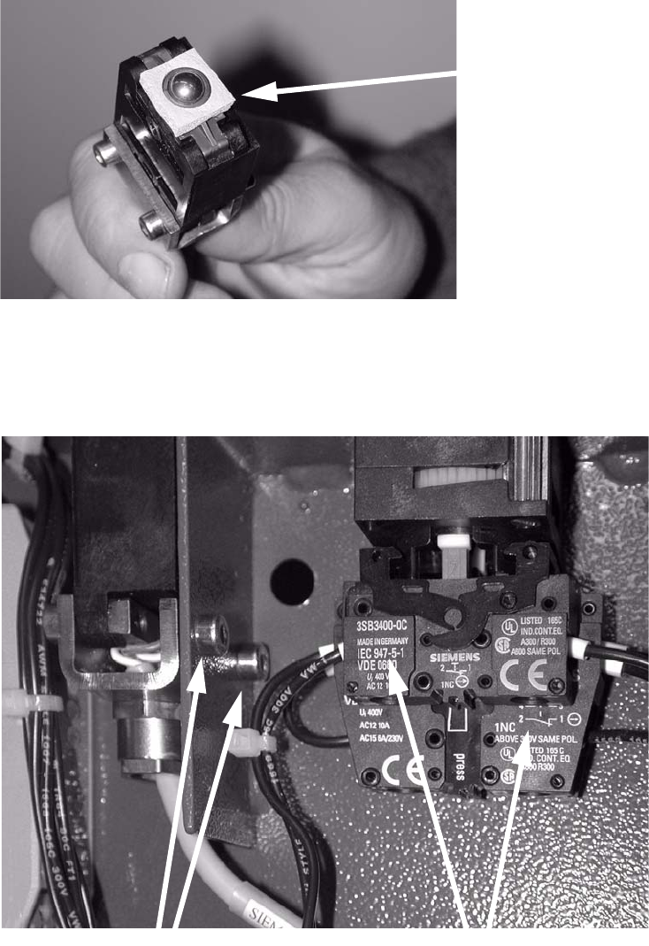
: Before installing, place the seal around the index ball.
2
2
: Insert the switch and screw it in place.
Clip the switch on the right in order to tighten the bottom screw.
2
2
2
Seal
Tighten 2 screws
Clip these two switches