00193892-0402_AI_FeederCoverFlap_DE+EN.pdf - 第56页
Assembly instructions Feeder cover flap, SIPLACE HF-series / X-series / D3 05/2009 Edition 56 : Adjust the plates with the four screws so th at the he adless set screws hit the actuators right in the middle. T o adjust t…

Assembly instructions Feeder cover flap, SIPLACE HF-series / X-series / D3
05/2009 Edition
55
Adjusting the damper 2
2
When the damper is right adjusted the plate should close by itself when it is pushed a little bit in
approximately 2 seconds. If it closes to fast or to hard, or the plate cannot close by itself you have
to re-adjust the damping force until everything is working correctly. 2
2
: Pull the damper to his full length. Twist the damper from the left to the right while you keep on
pulling until you can feel it locking.
: Now you can adjust the damping force by turning the damper to the left or to the right.
left => decrease damping force
right=> increase damping force.
: When the damper is right adjusted secure the damper to the ball joint at the empty tape guide
channel with the spring.
2
2
2
2
2
2
2
2
2
2
2
2
2
2
2
2
2
2
2
2
Assembly instructions Feeder cover flap, SIPLACE HF-series / X-series / D3
05/2009 Edition
56
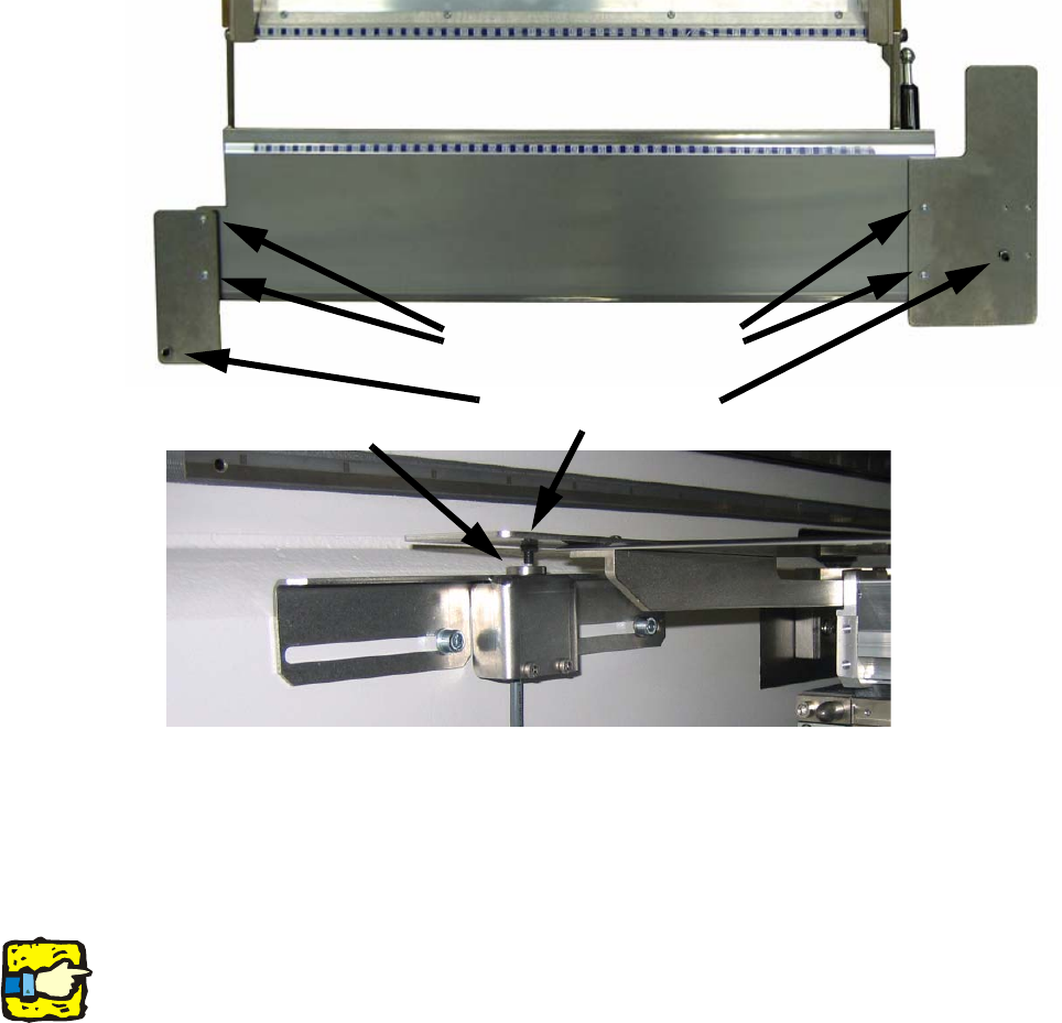
: Adjust the plates with the four screws so that the headless set screws hit the actuators right
in the middle. To adjust this position the switch at the machine frame can also be moved in Y-
direction.
2
2
: Install the nozzle changer if present
: Connect the machine to the power supply.
: Switch on the placement system.
2
Do not execute a reference run, because the feeder protective plate is not already right adjusted
and may cause a head crash. 2
2
: Put in the changover table.
: Shut down the station computer.
: Switch off the placement system.
2
2
Screws to adjust the plates
Headless set screws
Actuator
Assembly instructions Feeder cover flap, SIPLACE HF-series / X-series / D3
05/2009 Edition
57
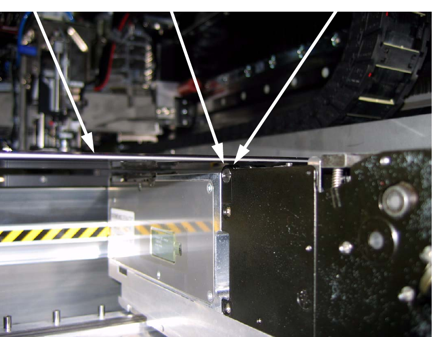
: Put a feeder on the outer left track and the outer right track and on the middle of the
changeover table.
: Adjust the height of the feeder protective plate with the left and the right headless set screw,
so that the distance between the bottom of the plate and the highest point of the feeder is about
1mm. The plate must not hit the feeders. Fix the screws with the screw nuts. Secure the screws
afterwards with screw locking paint.
2
2
: Repeat the described work steps at all locations where Feeder cover flaps should be installed.
2
: Turn on the machine and check the correct function of the protective plates.
: Before you execute a reference run, push the gantry carefully across the plate to make sure,
that there is enough space between the nozzle and the plate.
: Calibrate the nozzle changer and the nozzle removal unit.
2
protective
plate
distance between plate and
feeder should be about 1 mm
highest point of the feeder
(here a 2x8mm S feeder)