00193892-0402_AI_FeederCoverFlap_DE+EN.pdf - 第70页
Assembly instructions Feeder cover flap, SIPLACE HF-series / X-series / D3 05/2009 Edition 70 2.6.6 Assembly for SIPLACE HF-series (from A-001) : Loosen the screws on the side wall and remove the wa ll (four screws on th…
Assembly instructions Feeder cover flap, SIPLACE HF-series / X-series / D3
05/2009 Edition
69
: Reattach the feeder cover flap.
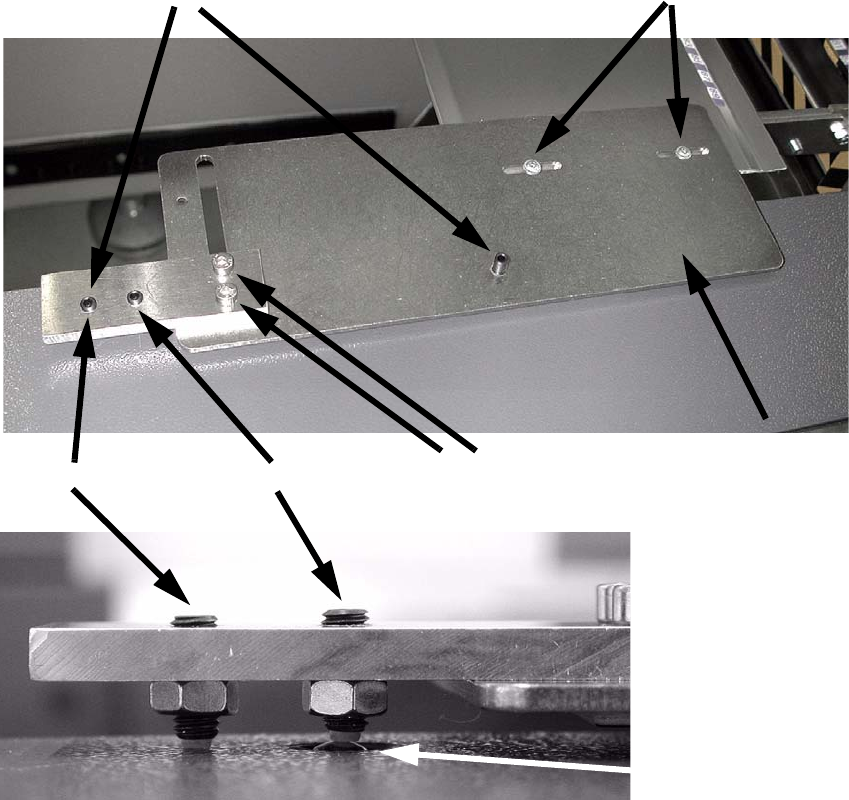
: Adjust the cover flap in the X and Y directions so that the inner screw presses onto the switch.
2
2
: Set the height using the screws shown in the top picture.
Adjust the outer screw so that the switch is reliably actuated, but so that the entire force of the
inner screw does not press onto the switch.
2
: Carry out the described tasks in all placement areas.
2
Inner screw
Switch
2 screws for adjusting in the X direction
2 screws for adjusting the height
2 screws for adjusting in the Y direction
Outer screw
Assembly instructions Feeder cover flap, SIPLACE HF-series / X-series / D3
05/2009 Edition
70
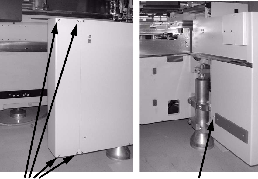
2.6.6 Assembly for SIPLACE HF-series (from A-001)
: Loosen the screws on the side wall and remove the wall (four screws on the outside and one
on the inside).
2
2
2
2
2
2
2
2
2
2
2
2
4 screws
1 screw
Assembly instructions Feeder cover flap, SIPLACE HF-series / X-series / D3
05/2009 Edition
71
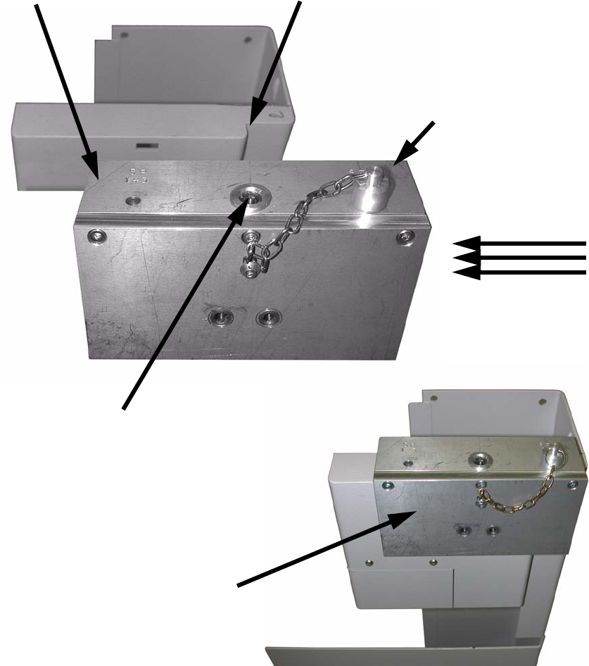
: Insert the pin into the drilling gauge as follows:
Location 1 + 3: Insert pin on the left,
Location 2 + 4: Insert pin on the right (see photograph).
: Push the drilling gauge (item no.: 03011814-01) on from the outside (in this case from the right)
until the pin lies against the recess.
2
2
2
Pin inserted on the
right, location 2 + 4
Hole for pin, location 1 + 3 Recess: Stop for pin
Drill hole
Drilling gauge in place
(item no.: 03011814-01)