00193892-0402_AI_FeederCoverFlap_DE+EN.pdf - 第71页
Assembly instructions Feeder cover flap, SIPLACE HF-series / X-series / D3 05/2009 Edition 71 : Insert the pin into the drilling gauge as follows: Location 1 + 3: Insert pi n on the left, Location 2 + 4: Insert pin on th…
Assembly instructions Feeder cover flap, SIPLACE HF-series / X-series / D3
05/2009 Edition
70
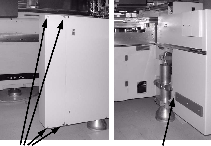
2.6.6 Assembly for SIPLACE HF-series (from A-001)
: Loosen the screws on the side wall and remove the wall (four screws on the outside and one
on the inside).
2
2
2
2
2
2
2
2
2
2
2
2
4 screws
1 screw
Assembly instructions Feeder cover flap, SIPLACE HF-series / X-series / D3
05/2009 Edition
71
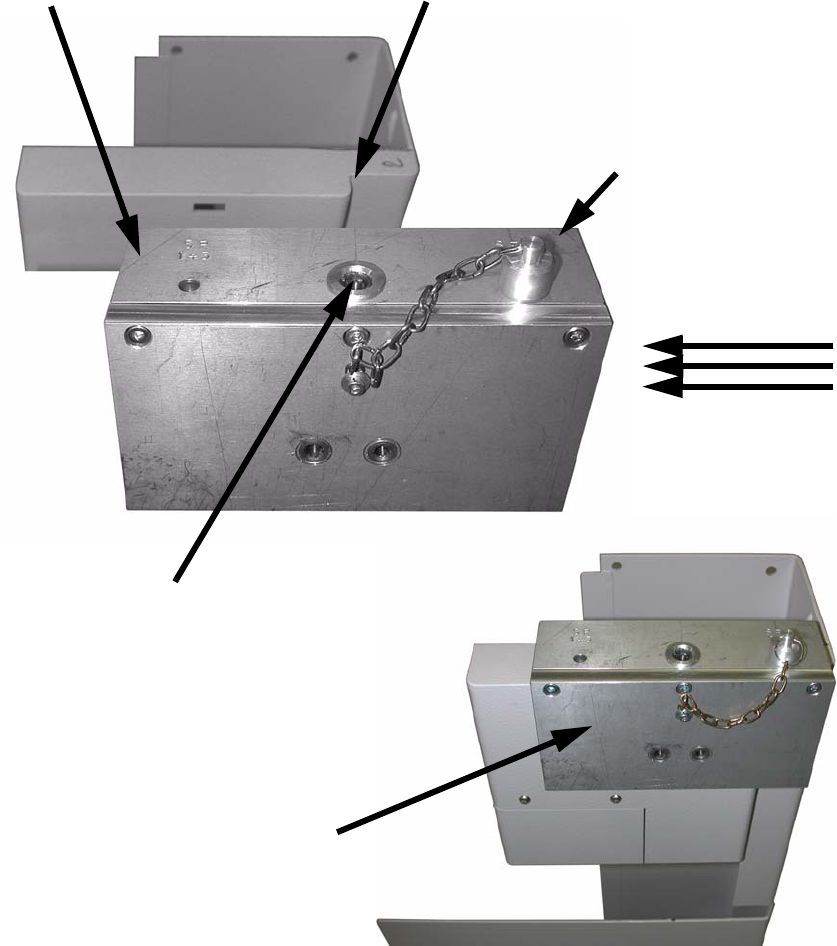
: Insert the pin into the drilling gauge as follows:
Location 1 + 3: Insert pin on the left,
Location 2 + 4: Insert pin on the right (see photograph).
: Push the drilling gauge (item no.: 03011814-01) on from the outside (in this case from the right)
until the pin lies against the recess.
2
2
2
Pin inserted on the
right, location 2 + 4
Hole for pin, location 1 + 3 Recess: Stop for pin
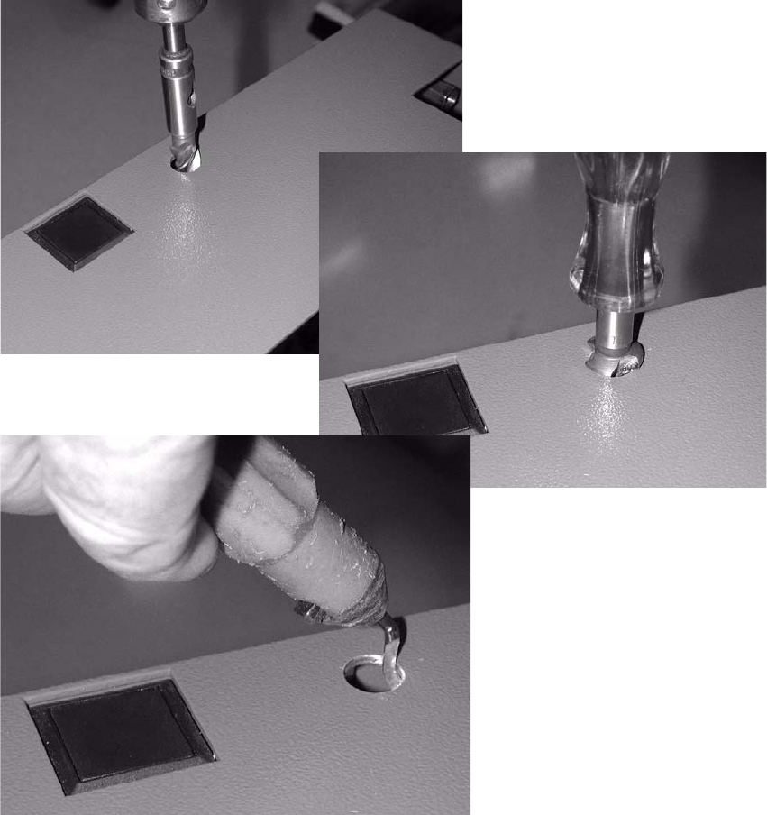
Drill hole
Drilling gauge in place
(item no.: 03011814-01)
Assembly instructions Feeder cover flap, SIPLACE HF-series / X-series / D3
05/2009 Edition
72
: Drill the 3 holes with a 5 mm diameter metal drill bit.
: Place the counterbore in the drilled hole and thus drill a larger hole (see photograph).
: Carefully deburr the drill hole inside and out.
2
2
2
2
2
2