00193892-0402_AI_FeederCoverFlap_DE+EN.pdf - 第69页
Assembly instructions Feeder cover flap, SIPLACE HF-series / X-series / D3 05/2009 Edition 69 : Reattach the feeder cover flap. : Adjust the cover flap in the X and Y directions so th at the inner screw pr esses onto the…
Assembly instructions Feeder cover flap, SIPLACE HF-series / X-series / D3
05/2009 Edition
68
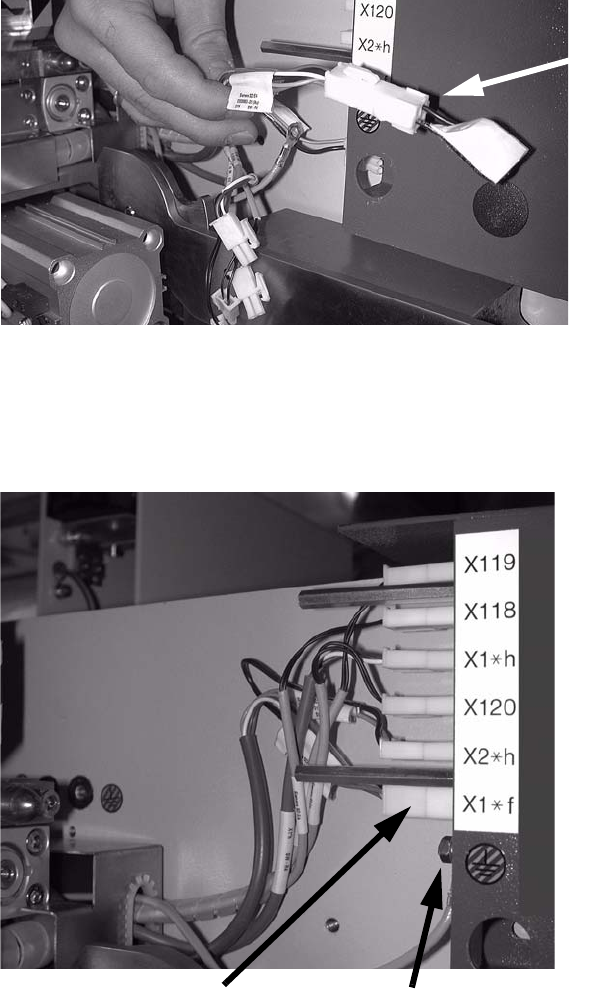
The connecting cable for the feeder cover flap with jumper can be found with the other connecting
cables. 2
: Remove the jumper.
2
2
: Plug in all the connectors in the correct positions (see photograph below).
: Screw on the grounding.
2
2
2
Remove the jumper
New connector
Grounding
Assembly instructions Feeder cover flap, SIPLACE HF-series / X-series / D3
05/2009 Edition
69
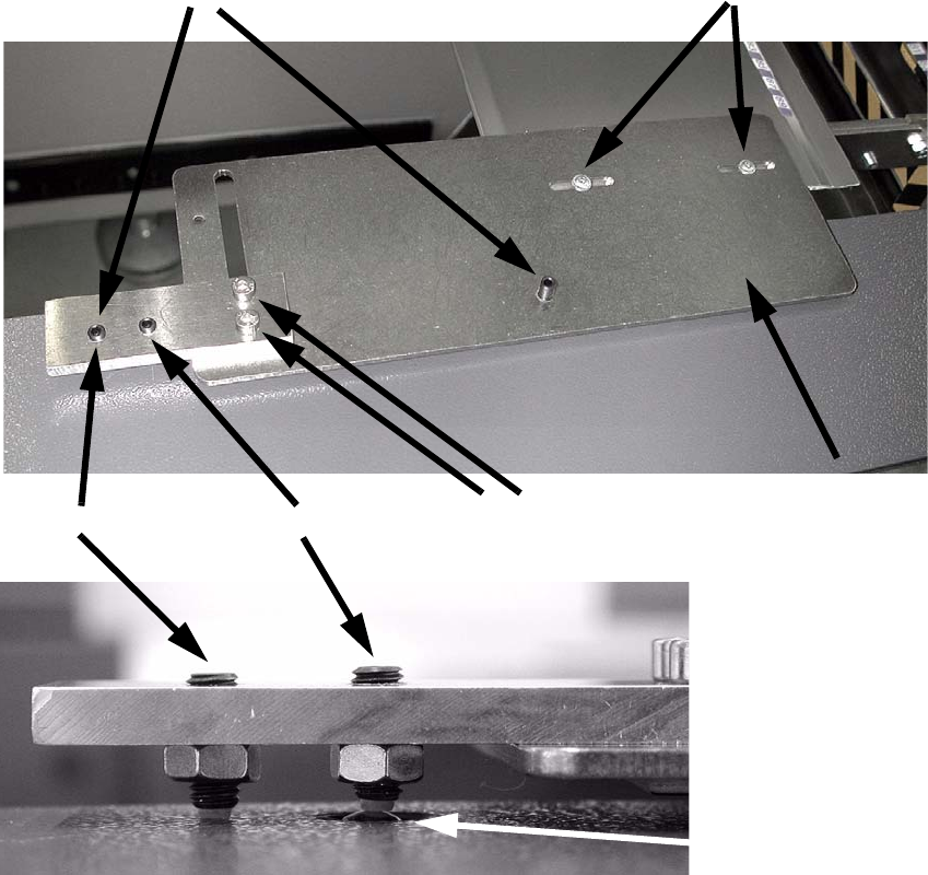
: Reattach the feeder cover flap.
: Adjust the cover flap in the X and Y directions so that the inner screw presses onto the switch.
2
2
: Set the height using the screws shown in the top picture.
Adjust the outer screw so that the switch is reliably actuated, but so that the entire force of the
inner screw does not press onto the switch.
2
: Carry out the described tasks in all placement areas.
2
Inner screw
Switch
2 screws for adjusting in the X direction
2 screws for adjusting the height
2 screws for adjusting in the Y direction
Outer screw
Assembly instructions Feeder cover flap, SIPLACE HF-series / X-series / D3
05/2009 Edition
70
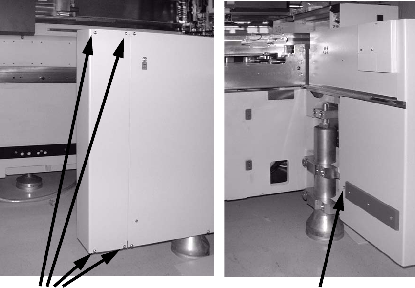
2.6.6 Assembly for SIPLACE HF-series (from A-001)
: Loosen the screws on the side wall and remove the wall (four screws on the outside and one
on the inside).
2
2
2
2
2
2
2
2
2
2
2
2
4 screws
1 screw