00193892-0402_AI_FeederCoverFlap_DE+EN.pdf - 第60页
Assembly instructions Feeder cover flap, SIPLACE HF-series / X-series / D3 05/2009 Edition 60 : Unplug the co nnectors and unscrew the gr ounding. 2 2 2 The jumper on the connector fo r the feeder cover flap is connected…
Assembly instructions Feeder cover flap, SIPLACE HF-series / X-series / D3
05/2009 Edition
59
2.6.4 Preparatory work
: Open the protective cover of the relevant gantry.
: Push the gantry out of the component table area until it is over the PCB feeder area.
: Dock the component trolleys out of the placement machine.
: Switch the placement machines off at the main switch.
2.6.5 Assembly for SIPLACE HF-series (up to A-001)
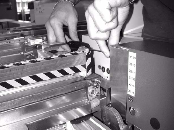
: Loosen the screws on the cover over the connections and remove the cover.
2
2
2
2
2
2
2
2
2
2
2
Assembly instructions Feeder cover flap, SIPLACE HF-series / X-series / D3
05/2009 Edition
60
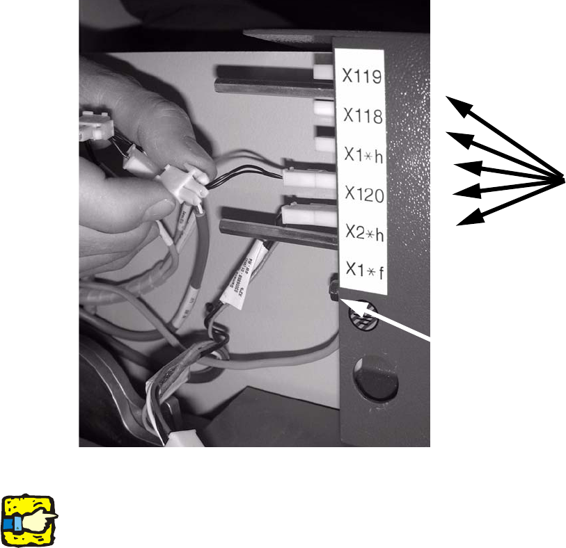
: Unplug the connectors and unscrew the grounding.
2
2
2
The jumper on the connector for the feeder cover flap is connected at the cables to be removed.2
2
2
2
2
2
2
2
2
2
2
2
Grounding
5 connectors
Assembly instructions Feeder cover flap, SIPLACE HF-series / X-series / D3
05/2009 Edition
61
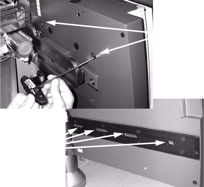
: Loosen the two top screws and four bottom screws on the outer panel of the component pull-
in device.
2
2
: Pull the panel forward to remove and set it down on the inside.
This will expose the electrical components in the panel.
2
2
2
2
2
2
2
2 screws at the top
4 screws at the bottom