00193892-0402_AI_FeederCoverFlap_DE+EN.pdf - 第62页
Assembly instructions Feeder cover flap, SIPLACE HF-series / X-series / D3 05/2009 Edition 62 : Unscrew any bolts from the p anel so that you can attach the drilling gauge. 2 2 : Unclip these t wo switches. 2 Bolts Screw…
Assembly instructions Feeder cover flap, SIPLACE HF-series / X-series / D3
05/2009 Edition
61
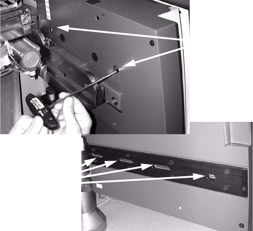
: Loosen the two top screws and four bottom screws on the outer panel of the component pull-
in device.
2
2
: Pull the panel forward to remove and set it down on the inside.
This will expose the electrical components in the panel.
2
2
2
2
2
2
2
2 screws at the top
4 screws at the bottom
Assembly instructions Feeder cover flap, SIPLACE HF-series / X-series / D3
05/2009 Edition
62
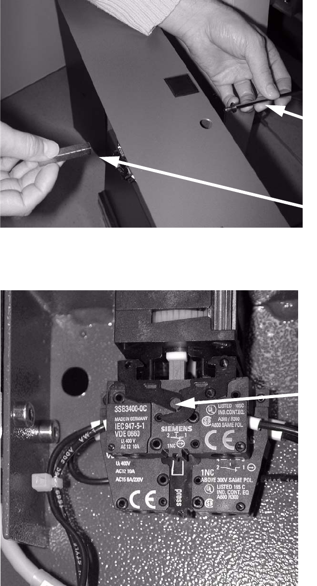
: Unscrew any bolts from the panel so that you can attach the drilling gauge.
2
2
: Unclip these two switches.
2
Bolts
Screw
Two switches
Assembly instructions Feeder cover flap, SIPLACE HF-series / X-series / D3
05/2009 Edition
63
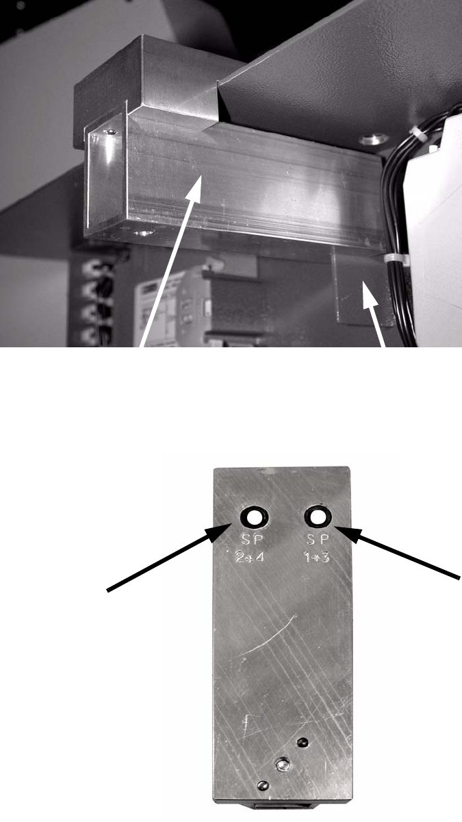
: Attach the drilling gauge as shown in the photograph.
2
The drilled hole must be selected to suit the location: 2
2
Drilling gauge (item no.: 03033936-01)
Partition in the side panel
Drill hole for
locations 1 and 3
Drill hole for
locations 2 and 4