00193892-0402_AI_FeederCoverFlap_DE+EN.pdf - 第59页
Assembly instructions Feeder cover flap, SIPLACE HF-series / X-series / D3 05/2009 Edition 59 2.6.4 Prep aratory work : Open the protective cover of the relevant gantry . : Push the gantry out of the compone nt table ar …
Assembly instructions Feeder cover flap, SIPLACE HF-series / X-series / D3
05/2009 Edition
58
2.6 Assembly Feeder cover flap (old version)
2.6.1 Overview
These flaps are not available any more. This manual is only necessary for a spare parts assembly.
The feeder cover flap is assembled in the same way on
both sides of the machine, only the other
way around. The manual shows photographs of both sides. 2
2.6.2 Restriction
The “Feeder Protection SIPLACE HF” can not be used in conjunction with the 6-nozzle revolver
head and nozzle types 820, 821, 921. When these short nozzles are used the segment touches
the protection plate before the nozzle touches the part in the pocket. 2
2.6.3 Tools and consumables required
– Set of hexagon socket spanners
– Caliper gauge
– Power drill or cordless screwdriver
– Metal drill bit (5 mm)
– Counterbore (5 mm at the tip / 12 mm at the shaft)
– Rose bit
– Deburrer
Additionally for HF-series up to A-001: 2
– Drilling gauge (item no.: 03033639-01)
Additionally for HF-series from A-001 / X-series: 2
– Drilling gauge (item no.: 03011814-01)
Assembly instructions Feeder cover flap, SIPLACE HF-series / X-series / D3
05/2009 Edition
59
2.6.4 Preparatory work
: Open the protective cover of the relevant gantry.
: Push the gantry out of the component table area until it is over the PCB feeder area.
: Dock the component trolleys out of the placement machine.
: Switch the placement machines off at the main switch.
2.6.5 Assembly for SIPLACE HF-series (up to A-001)
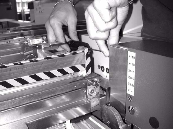
: Loosen the screws on the cover over the connections and remove the cover.
2
2
2
2
2
2
2
2
2
2
2
Assembly instructions Feeder cover flap, SIPLACE HF-series / X-series / D3
05/2009 Edition
60
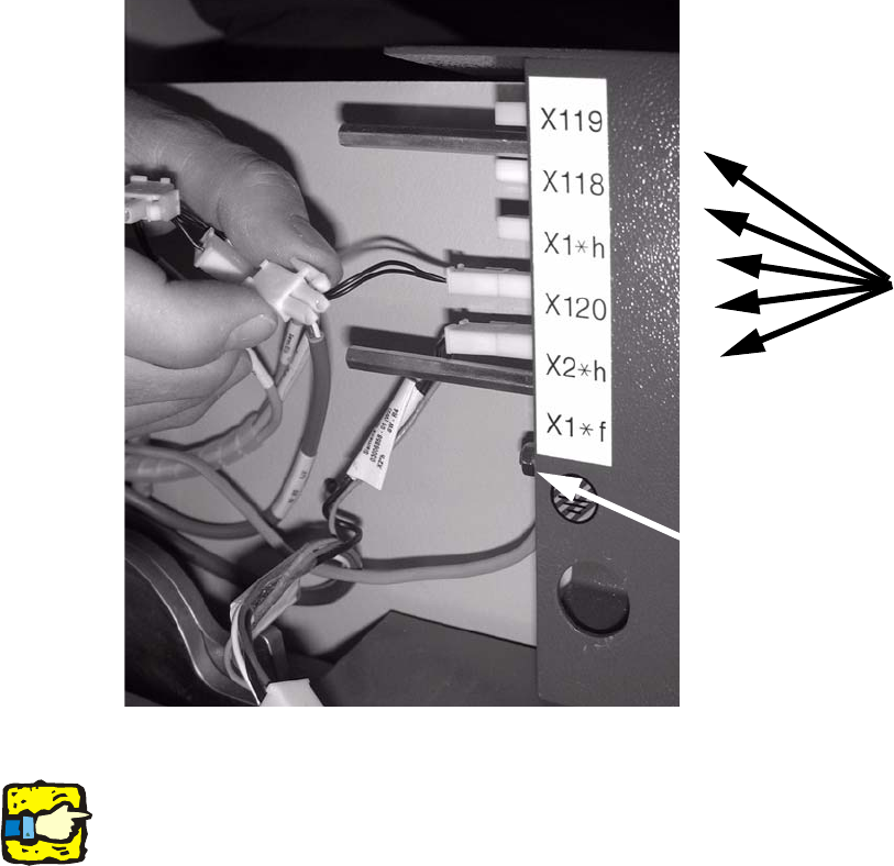
: Unplug the connectors and unscrew the grounding.
2
2
2
The jumper on the connector for the feeder cover flap is connected at the cables to be removed.2
2
2
2
2
2
2
2
2
2
2
2
Grounding
5 connectors