3OM-1751-002w_G5S.pdf - 第107页
3OM-1751 1-53 1303-001 • T eaching V acuum Nozzle For the head rotation axis offset teaching, the two jig nozzles (standard equipment) and one normal vacuum nozzles HV19C. Before the teaching operation, change the nozzle…
3OM-1751
1-521303-001
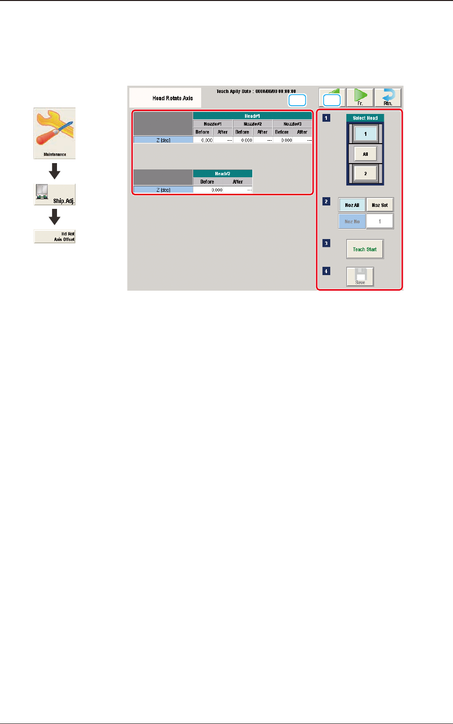
5.10 "Head Rotate Axis" Window
These offsets are used to correct the deviations for the head movement to the
camera.
[1] [2]
F3A38
[1] Teaching Data Display Section
Displayed are the offset data items for the designated head.
[2] Teaching Procedure Display Area
Displayed are the buttons to be used for the teaching operations.
Select Head
Each head in the graphic image is provided with a button function. Select the
head for which the teaching operation is performed.
[Noz All] button
When pressed, the teaching operation for all the nozzles is performed.
[Noz Set] button
Using this button, the nozzle to be taught is designated.
When the [Noz Set] button is pressed, the parameter input window appears.
[Teach Start] button
When pressed, this button executes the teaching operation.
[Save] button
When this button is pressed, the teaching results are saved.
Graphic
Development
5.10 "Head Rotate Axis" Window

3OM-1751
1-531303-001
•
Teaching Vacuum Nozzle
For the head rotation axis offset teaching, the two jig nozzles (standard
equipment) and one normal vacuum nozzles HV19C. Before the teaching
operation, change the nozzles in the "NOZ.CHNG." window (Operation
Sequence: Select [Unit Adj.] button in the Menus for Maintenance
→
Select
[Noz Chng.] button).
At that time, attach the nozzles onto the nozzle No. 1 positions.
·
Teaching Procedure
Procedure
(1) Select the head (1, 2 or All) for which the head rotation axis offset teaching
is performed.
Note
In the case that the multi-functional head is selected, select the nozzle to be
taught and press the [Teach Start] button.
(2) Press the [Teach Start] button.
(The designated beam will be moved to the specied position and the head
rotation axis offset is taught.)
•
When the teaching is started, the start conditions are checked.
•
During this temporary stop mode, the selection of any other menu item is
unavailable.
When the offset teaching is completed, the designated head returns to the
home position automatically.
The teaching results are displayed in the "Beam XY Offset Conrmation"
Display Area.
(3) Press the [Save] button.
(When this button is pressed, the teaching results are saved.)
5.10 "Head Rotate Axis" Window
3OM-1751
1-541303-001
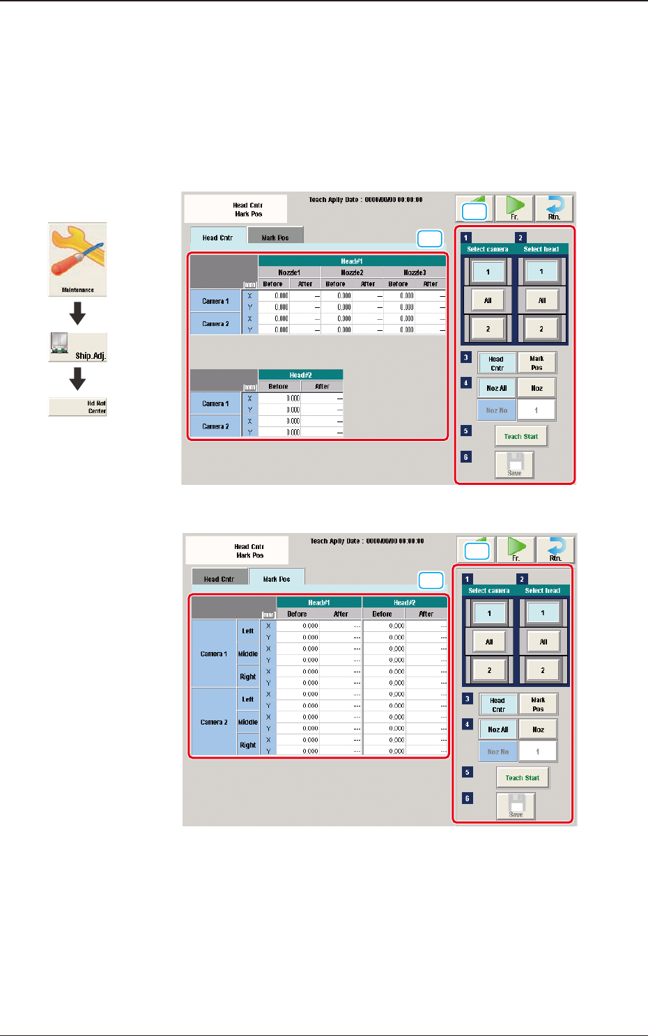
5.11 "Head Cntr Mark Pos" Window
In this window, the teaching for the offset data is performed to correct the
deviation of the head rotation center from the PEC recognition camera center
reference value. Also, the reference mark position is taught, which was caught
using the PEC recognition camera when the head rotation center is moved onto
the component recognition camera view.
[1]
[2]
"Head Cntr" tab sheet F3A39
[1]
[2]
"Mark Pos" tab sheet F3A40
Graphic
Development
5.11 "Head Cntr Mark Pos" Window