3OM-1751-002w_G5S.pdf - 第216页
3OM-1751 2-48 2.6.1 "Nozzle Level A" T ab Sheet [1] [2] F3B47 [1] Nozzle In this section, each nozzle No. is displayed. [2] Head 1 and Head 2 L (Height) [mm] Each parameter indicates the offset of the bottom le…
3OM-1751
2-471303-001
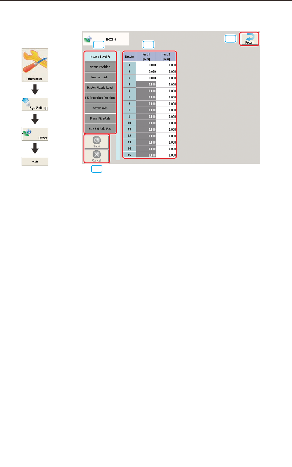
2.6 "Nozzle" Window
[1] [2]
[3]
[4]
F3B46
[1] Offset button
When this button is pressed, the offset data for the selected tab is displayed.
[2] Offset Data Display Section
In this section, the offset data selected in step [1] is displayed.
[3] [Return] button
When this button is pressed, the "Offset Data" window is returned.
[4] [Save] button
When this button is pressed, the input data is saved.
[Cancel] button
When this button is pressed the input data is cancelled and the saved data is
returned.
2.6 "Nozzle" Window
Graphic
Development
3OM-1751
2-48
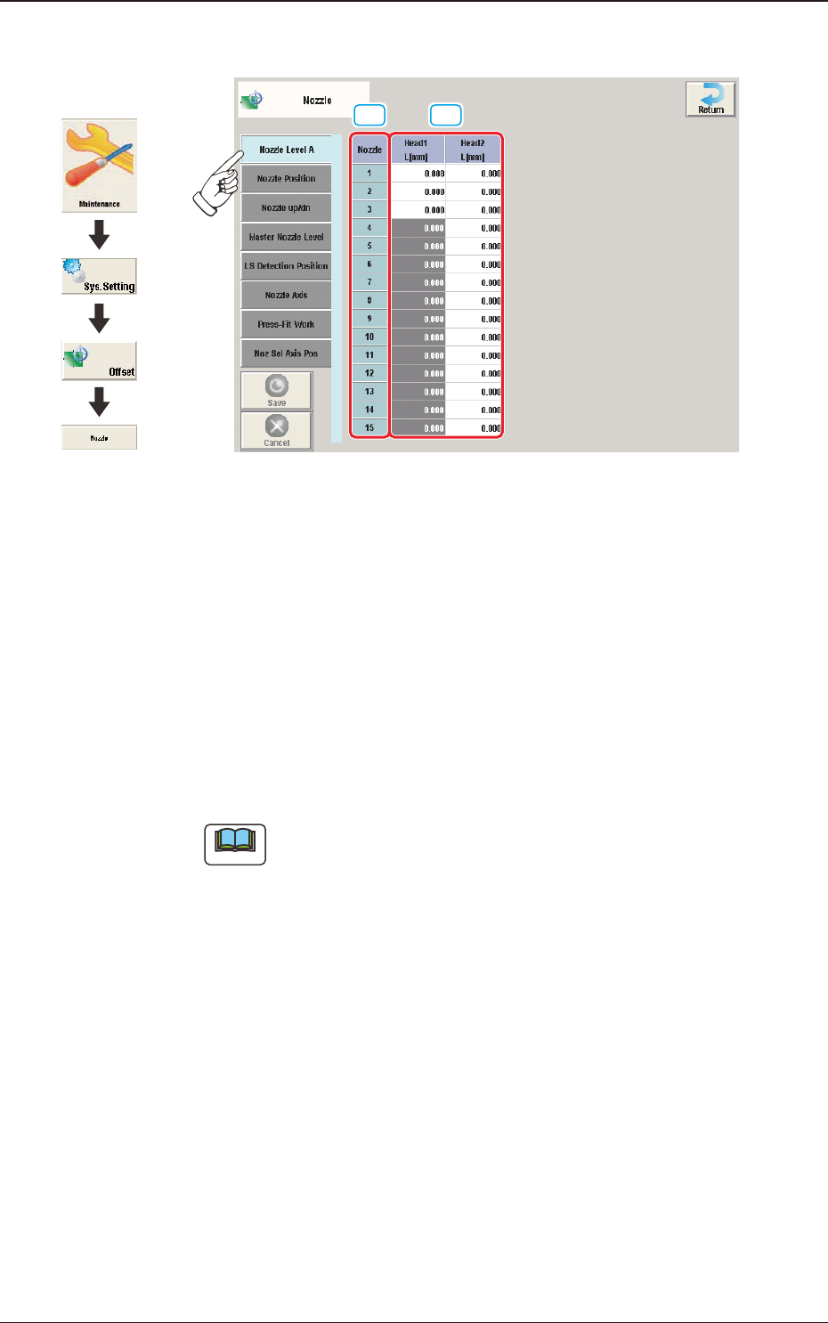
2.6.1 "Nozzle Level A" Tab Sheet
[1] [2]
F3B47
[1] Nozzle
In this section, each nozzle No. is displayed.
[2] Head 1 and Head 2
L (Height) [mm]
Each parameter indicates the offset of the bottom level of the normal nozzles
on each individual heads.
Measure each nozzle bottom level with a linear measure while the nozzle U/
D axis is zeroed and save the difference between the level and the master
nozzle level offset.
Note
These parameters are calculated using the formula "Nozzle Level Offset =
Master Nozzle Level - Measured Value of Normal Nozzle Level".
1303-001
2.6 "Nozzle" Window
Graphic
Development
3OM-1751
2-491303-001
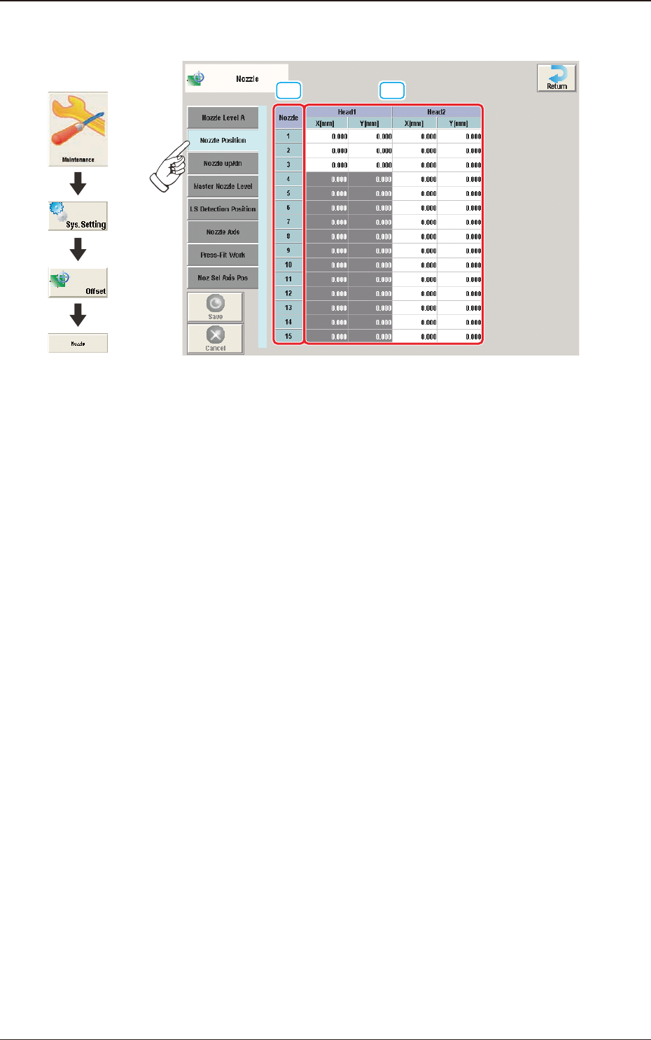
2.6.2 "Nozzle Position" Tab Sheet
[1] [2]
F3B48
[1] Nozzle
In this section, each nozzle No. is displayed.
2.6 "Nozzle" Window
Graphic
Development