3OM-1751-002w_G5S.pdf - 第179页
3OM-1751 2-1 1 1303-001 2.1.6 "T each Plate" T ab Sheet [1] F3B11 [1] Head 1 and Head 2 X (Horizontal), Y (V ertical), and L (Height) [mm] Enter the parameters required to adjust the deviations based on the des…
3OM-1751
2-10
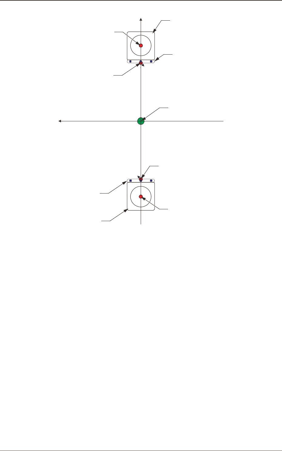
Xm(+)
Ym(+)
Component Recognition
Camera
Head Rotational Center
Standard Mark
Center of PEC Recognition
Camera
Pm. Machine Reference
Coordinate Origin
Standard Mark
Center of PEC Recognition
Camera
Component Recognition
Camera
Head Rotational Center
F3B10
1303-001
2.1 "Device Offset" Window

3OM-1751
2-111303-001
2.1.6 "Teach Plate" Tab Sheet
[1]
F3B11
[1] Head 1 and Head 2
X (Horizontal), Y (Vertical), and L (Height) [mm]
Enter the parameters required to adjust the deviations based on the design
position of the jig depot.
Graphic
Development
2.1 "Device Offset" Window

3OM-1751
2-121303-001
2.1.7 "Line Sensor" Tab Sheet
[1]
F3B12
[1] Head 1 and Head 2
Set the number of dirt detection scanning times to be conducted by the linear
measure sensor of each head.
Graphic
Development
2.1 "Device Offset" Window