3OM-1751-002w_G5S.pdf - 第238页
3OM-1751 2-70 1303-001 2.1 1 "Unit Of fset" Window F3B69 Note This setting is used as an option. Reference Refer to "V olume 7 : Multi-Layer T ray Feeder" for details. 2.1 1 "Unit Offset" Wi…
3OM-1751
2-691303-001
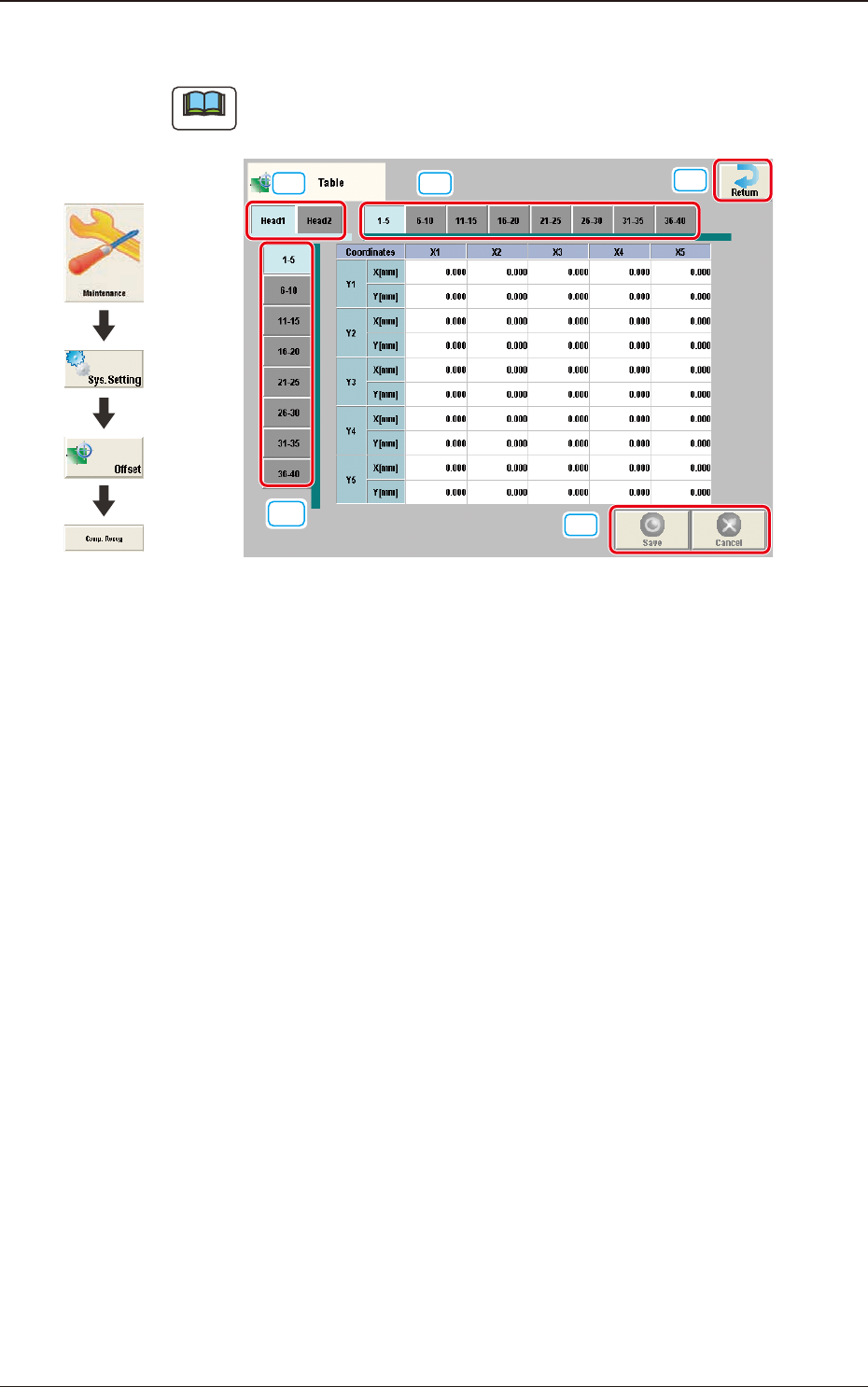
2.10 "Table" Window
Note
As for the "Head 2" tab sheets, the same contents as the "Head 1" tab sheet are
displayed.
[3]
[1] [2]
[4]
[5]
F3B68
Enter the amount of deviation based on the specied distance when Head 1 has
moved as far as the specied distance (each grid point, X Direction: X1 through
X40, Y Direction: Y1 through Y40) from the PCB positioning reference.
These values are calculated automatically through the teaching operation and
entered in each text box.
[1] Head Select Tab
Using this tab, the head to be input is selected.
[2] Direction "X" Select Tab
Using this tab, the point on the grid in the direction "X" for the selected tab,
is displayed.
[3] Direction "Y" Select Tab
Using this tab, the point on the grid in the direction "Y" for the selected tab,
is displayed.
[4] [Return] button
When this button is pressed, the "Offset Data" window is returned.
[5] [Save] button
When this button is pressed, the input data is saved.
[Cancel] button
When this button is pressed, the input data is cancelled and the save data is
returned.
2.10 "Table" Window
Graphic
Development
3OM-1751
2-701303-001
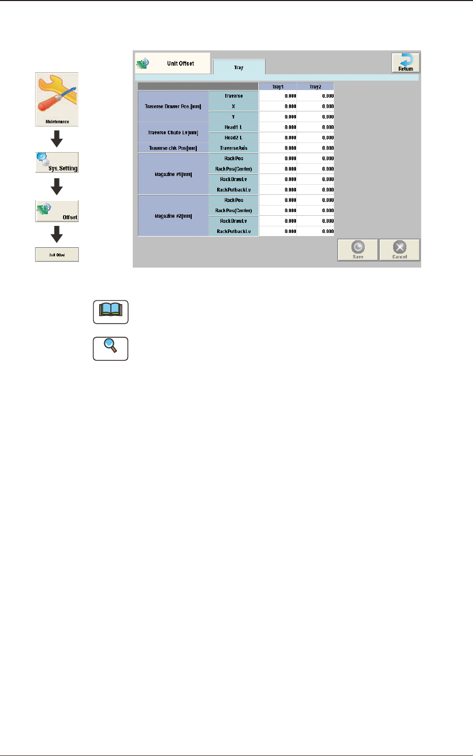
2.11 "Unit Offset" Window
F3B69
Note
This setting is used as an option.
Reference
Refer to "Volume 7 : Multi-Layer Tray Feeder" for details.
2.11 "Unit Offset" Window
Graphic
Development
3OM-1751
2-711303-001
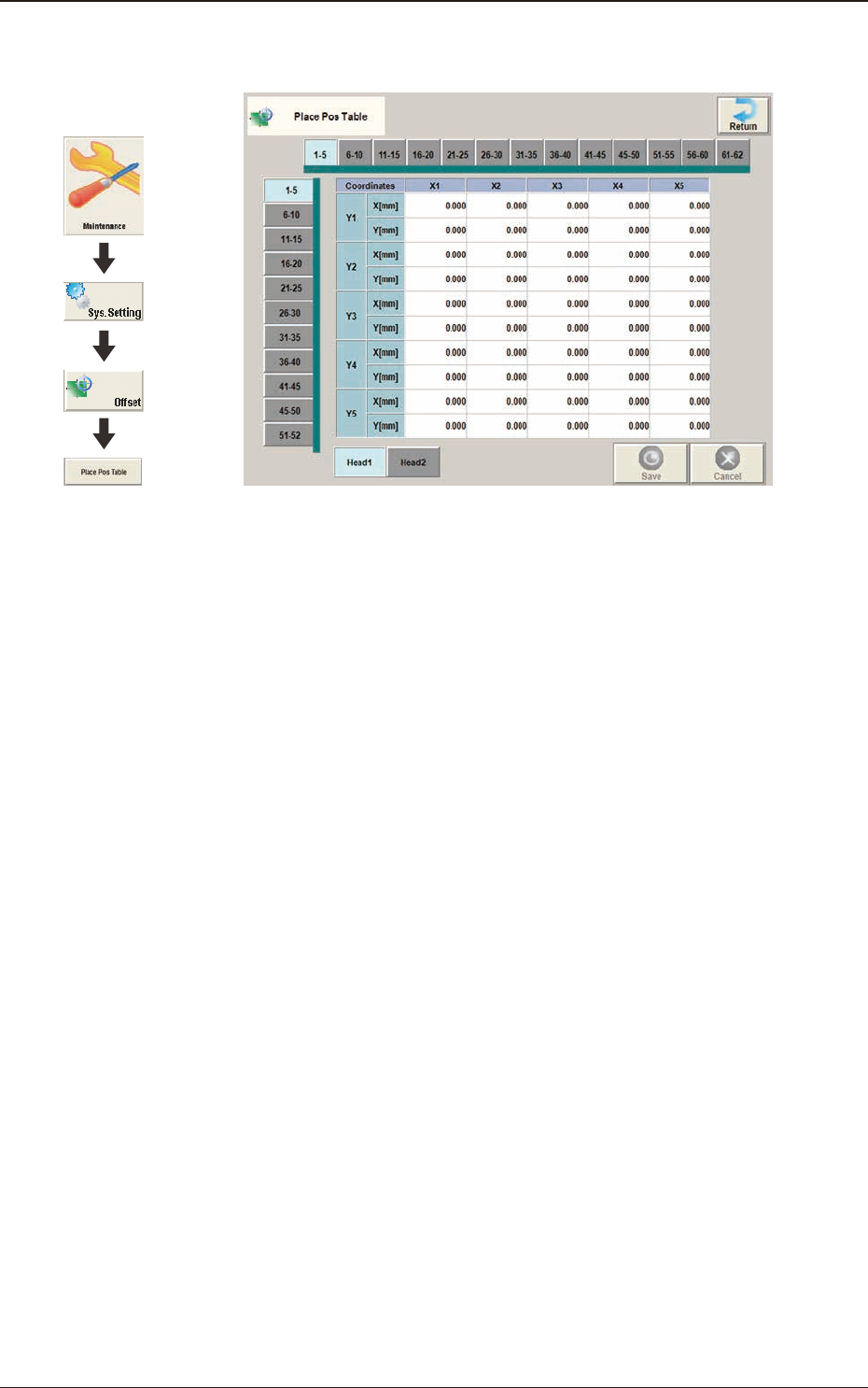
2.12 "Place Pos Table" Window
F3B70
2.12 "Place Pos Table" Window
Graphic
Development