3OM-1751-002w_G5S.pdf - 第194页
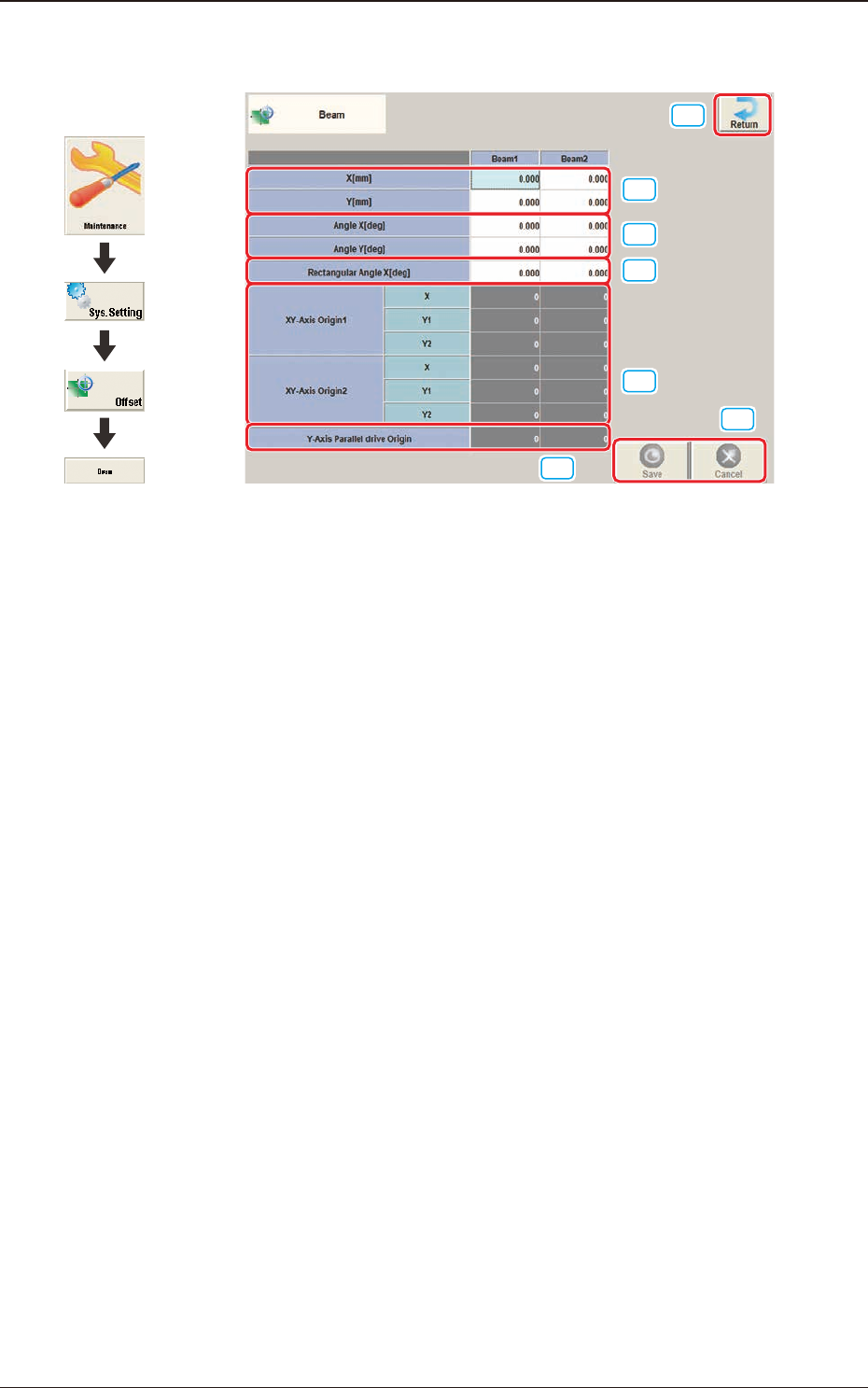
3OM-1751 2-26 1303-001 2.4 "Beam" Window [1] [2] [3] [6] [7] [4] [5] F3B26 [1] X (Horizontal) and Y (V ertical) [mm] The set parameters are used to adjust the positional deviation based on the design dimensions…

3OM-1751
2-251303-001
[4] [Ret] button
When this button is pressed, the "Offset Data" window is returned.
[5] [Save] button
When this button is pressed, the input data is applied.
[Cancel] button
When this button is pressed, the input data is cancelled and the save data is
returned.
2.3 "Feeder A" and "Feeder B" Window
3OM-1751
2-261303-001
2.4 "Beam" Window
[1]
[2]
[3]
[6]
[7]
[4]
[5]
F3B26
[1] X (Horizontal) and Y (Vertical) [mm]
The set parameters are used to adjust the positional deviation based on the
design dimensions representing the distance between the machine reference
coordinate origin and the center of the PEC recognition camera at the head
origin.
2.4 "Beam" Window
Graphic
Development
3OM-1751
2-271303-001
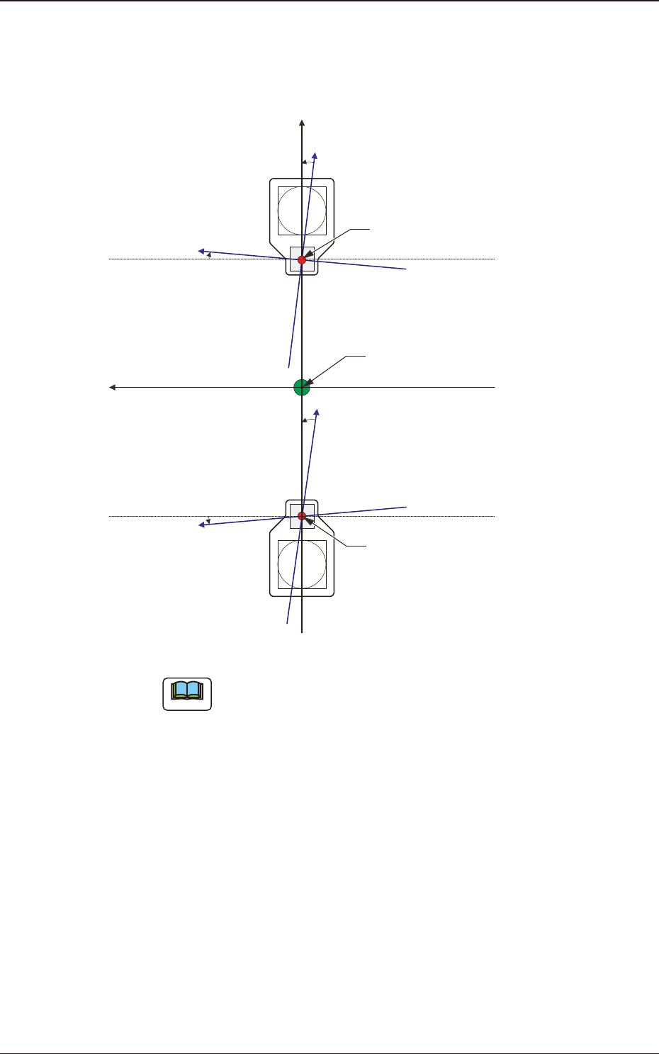
[2] Angle X and Angle Y [deg]
The set parameters are used to adjust the beam X and Y axes to the machine
reference coordinate system.
Xm(+)
Ym(+)
Yb(+)
Xb(+)
Yb(+)
Xb(+)
Head Origin
Pm. Machine Reference
Coordinate Origin
Head Origin
Xm-Ym
Xb-Yb
: Machine Reference
Coordinate System
: Real Beam Coordinate
System
F3B27
Note
A plus values must be entered in the "Angle X [deg]" and "Angle Y [deg]"
text boxes when the real beam coordinate system is tilted counterclockwise
(based on the machine reference coordinate system).
2.4 "Beam" Window