3OM-1751-002w_G5S.pdf - 第94页
3OM-1751 1-40 1303-001 5.5 "PCB Recog Light" Window The corresponding window enables you to perform a teaching operation on the lighting of the PEC recognition camera. [1] [2] [3] F3A30 [1] T eaching Data Displ…
3OM-1751
1-391303-001
·
Teaching Procedure
Note
Before performing the teaching operation, press the [ZERO] button in the
"Control" menu to zero all axes.
Procedure
(1) Select the component recognition camera for which the teaching is
performed, in the "Select Camera" section, and lighting pattern.
(2) Press the [XY Beam Save Pos] button and within 10 seconds, press the
[START] button on the operation panel.
Note
The lock for the transparent cover is undone automatically.
(3) Open the transparent cover and set-up the teaching jig for the component
recognition camera lighting on the component recognition camera according
to the lighting pattern.
Reference
Refer to "Teaching Jig Set-up Diagram" for the combination of the
component recognition lighting teaching jigs.
(4) Press the [JigSet Conf] button.
(5) Close the transparent cover and press the Cover Lock Switch ([Cover Ready]
button) on the main machine.
(The transparent cover will be locked).
(6) Press the [Teach Start] button and within 10 seconds, press the [START]
button on the operation panel.
(The corresponding window enables you to perform a teaching operation on
the lighting of the component recognition camera.)
(7) Press the Cover Lock Switch ([Cover Ready] button) on the main machine
and open the transparent cover in the corresponding block.
(8) Remove the set-up component recognition lighting teaching jigs.
Notice
Unless the lighting teaching jigs are removed, the head would be
damaged.
(9) Press the [JigDetach Conf] button.
(10) Press the [Save] button to save the teaching results.
(11) Close the transparent cover and press the Cover Lock Switch ([Cover Ready]
button).
5.4 "Cmp Recog Light" Window
3OM-1751
1-401303-001
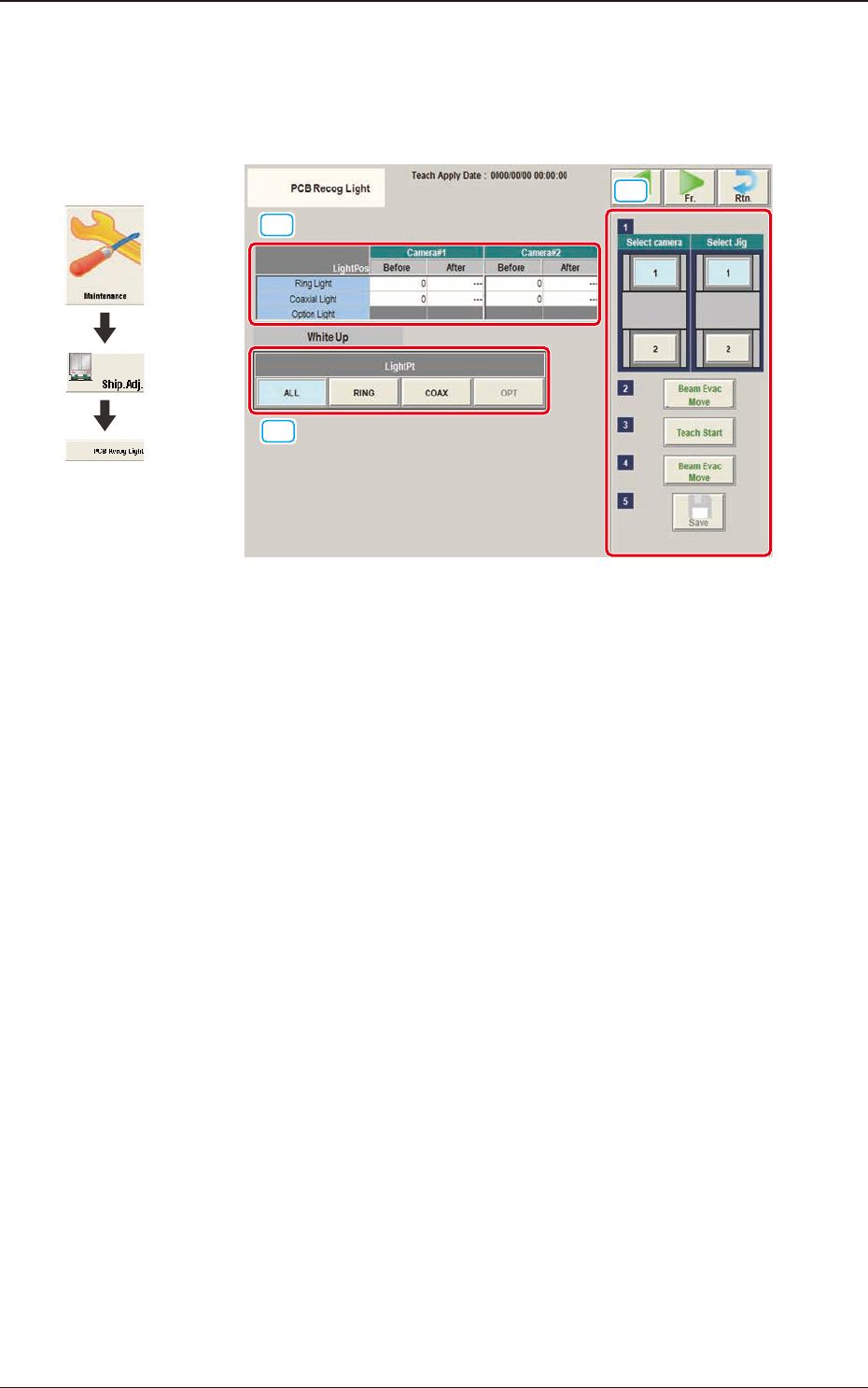
5.5 "PCB Recog Light" Window
The corresponding window enables you to perform a teaching operation on the
lighting of the PEC recognition camera.
[1]
[2]
[3]
F3A30
[1] Teaching Data Display Section
Displayed are offset data items for each lighting pattern for the designated
camera.
[2] Teaching Procedure Display Area
Displayed are the buttons to be used for the teaching operations.
Select camera
Each PEC recognition camera in the graphic image of the machine is
provided with a button function. When a button is pressed, the corresponding
PEC recognition camera is selected as an object one for the teaching
operation.
Select Jig
Select the block where the jig is set up.
[Beam Evac Move] button
When pressed, this button moves the XY beam to their home positions.
[Teach Start] button
When pressed, this button executes the teaching operation.
[Beam Evac Move] button
When pressed, this button moves the XY beam to their home positions.
Graphic
Development
5.5 "PCB Recog Light" Window
3OM-1751
1-411303-001
[Jig Detac Conrm.] button
When pressed, this button conrms the jig detachment.
[Save] button
When this button is pressed, the teaching results are saved.
[3] [Light Pt] button
The camera 1 or camera 2 lighting pattern is selected from the following
items.
ALL
: When selected, the teaching for the ring-lamp or coaxial lamp is
performed.
RING
: When selected, the teaching for the ring-lamp is performed.
COAX
: When selected, the teaching for the coaxial lamp is performed.
OPT
:
•
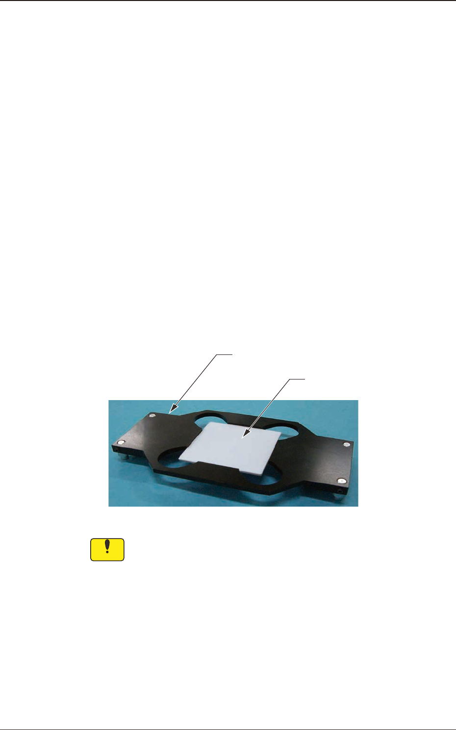
Teaching Jig for PEC Recognition Camera Lighting
The following jig components are used for the teaching on the PEC recognition
camera lighting. Before the teaching, combine the jig with the teaching glass jig
mounting support jig and place it on the PEC recognition camera.
After the teaching operation, remove it.
Teaching Glass Jig Mounting Support Jig
Teaching Glass Jig
(JG-0287,KYF-M8840-00)
(JG-0286,KYF-M8830-00)
F3A31
Notice
Set-up the teaching glass jig mounting support jig securely so that it does
not rise. If the mounting condition is not satisfactory, the head, etc., might
be damaged.
5.5 "PCB Recog Light" Window