3OM-1751-002w_G5S.pdf - 第224页
3OM-1751 2-56 1303-001 2.6.8 "Noz Sel Axis Pos" T ab Sheet [2] [1] F3B55 [1] Nozzle Each Nozzle No. is displayed in these boxes. [2] Head1, Head2 Z [Ang] These offset parameters are used to correct the position…
3OM-1751
2-551303-001
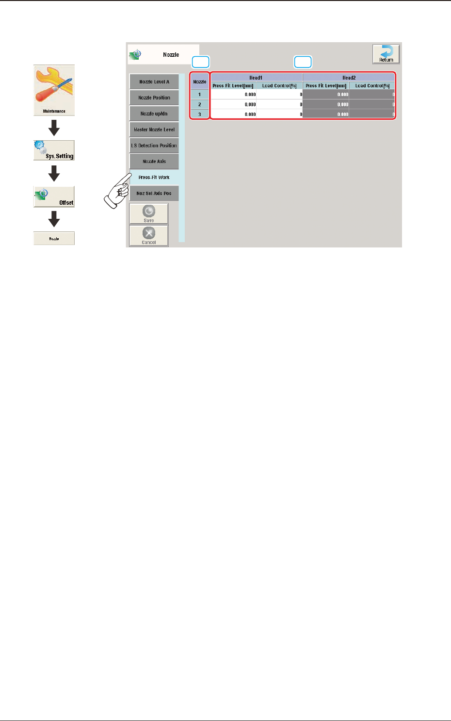
2.6.7 "Press-Fit Work" Tab Sheet
[1]
[2]
F3B54
[1] Nozzle
In this section, each nozzle No. is displayed.
[2] Head 1 and Head 2
Press Fit Level [mm]
The correction is performed when the nozzle attachment position is deviated
due to the component change in these text boxes.
Positive value reduces the operation range and negative value increases the
operation range.
2.6 "Nozzle" Window
Graphic
Development
3OM-1751
2-561303-001
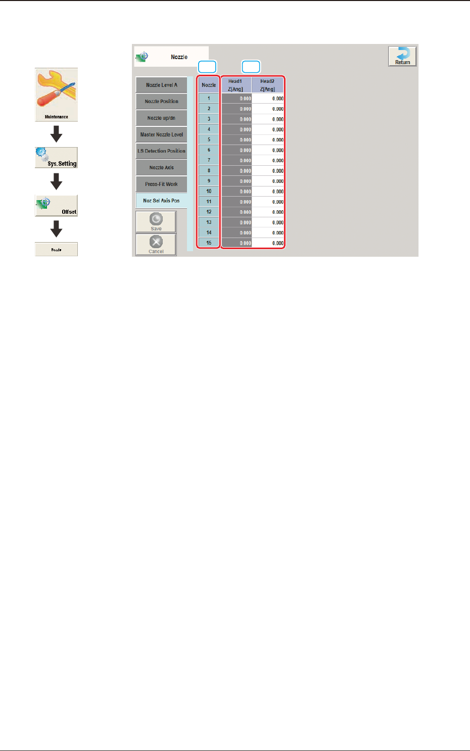
2.6.8 "Noz Sel Axis Pos" Tab Sheet
[2][1]
F3B55
[1] Nozzle
Each Nozzle No. is displayed in these boxes.
[2] Head1, Head2
Z [Ang]
These offset parameters are used to correct the position relation between the
nozzle selection axis and the nozzle.
2.6 "Nozzle" Window
Graphic
Development
3OM-1751
2-571303-001
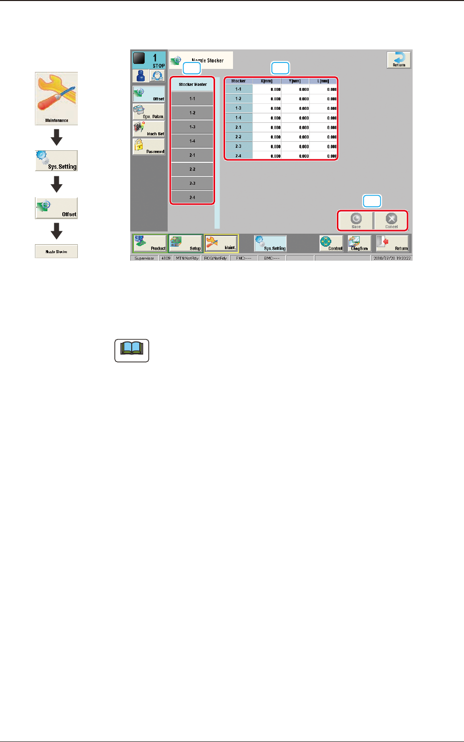
2.7 "Nozzle Stocker" Window
[3]
[2] [1]
F3B56
[1] Offset button
When this button is pressed, the offset data for the selected tab is displayed.
Note
When the
[Stocker Master]
button is pressed, the set values of 1-1
through 1-4 and 2-1 through 2-4 are displayed.
[2] Offset Data Display Section
In this section, the offset data selected in step [1] is displayed.
[3] [Save] button
When this button is pressed, the input data is saved.
[Cancel] button
When this button is pressed, the input data is cancelled and the save data is
returned.
2.7 "Nozzle Stocker" Window
Graphic
Development