3OM-1751-002w_G5S.pdf - 第207页
3OM-1751 2-39 1303-001 [3] Head Pivot Point The set parameters are used to adjust the deviations in the design value between the head rotational center and the center of the PEC recognition camera. Xm-Ym : Xm(+) Ym(+) He…
3OM-1751
2-381303-001
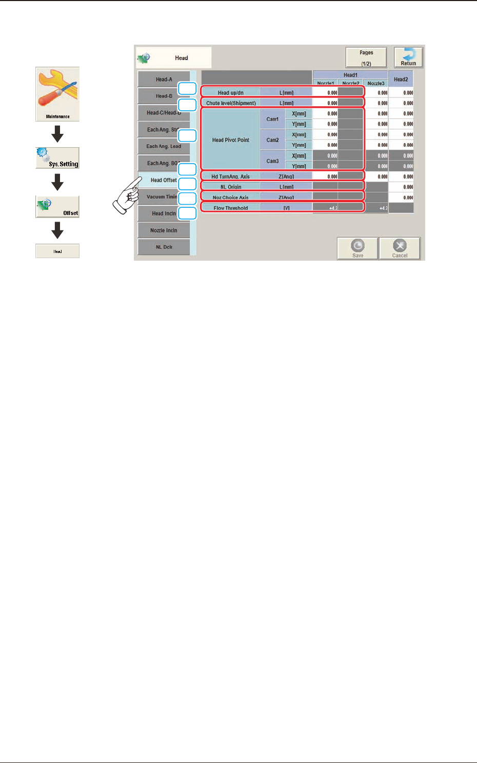
2.5.7 "Head Offset" Window
[1]
[3]
[2]
[4]
[5]
[6]
[7]
F3B37
[1] Head up/dn
The set parameters are used to adjust the deviations (caused when the master
nozzle is attached to the head and lowered by the specied distance with the
combined operations of the head and nozzle U/D axes) based on the design
value of the distance between the upper surface of PCB and the lower surface
of the nozzle. The amount of movement of each axis is separately reviewed.
When the measured value is greater than the design one, a plus sign must be
afxed to the offset data.
[2] Chute level (Shipment)
These offset parameters for backup are used to calculate the difference of
the chute level value in shipping from that in the head change, by means
of measuring the chute level in advance when the machine is shipped and
performing the chute level height teaching when the head is changed.
2.5 "Head" Window
Graphic
Development
3OM-1751
2-391303-001
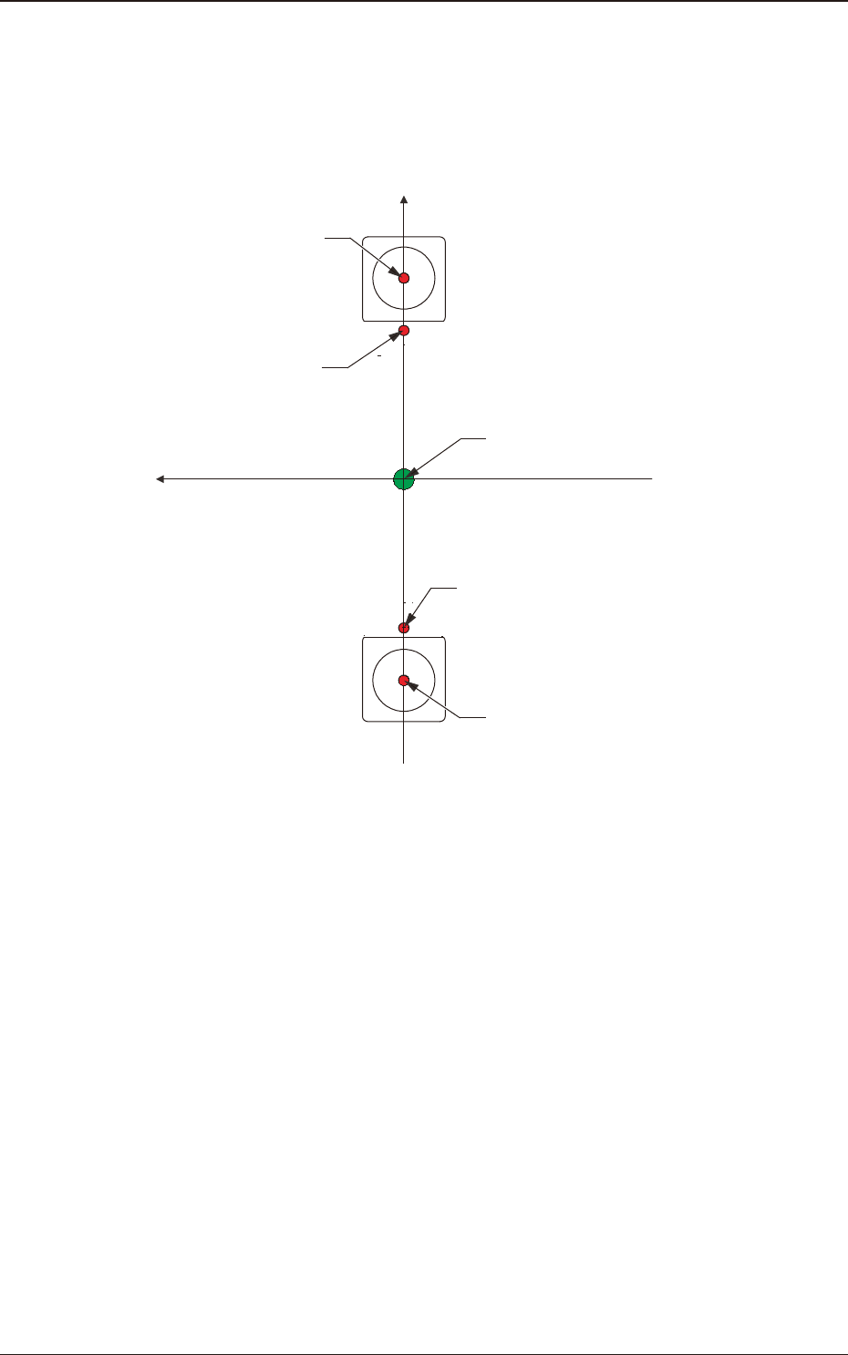
[3] Head Pivot Point
The set parameters are used to adjust the deviations in the design value
between the head rotational center and the center of the PEC recognition
camera.
Xm-Ym :
Xm(+)
Ym(+)
Head Pivot Point
Center of PEC Recognition
Camera
Pm. Machine Reference
Coordinate Origin
Center of PEC Recognition Camera
Head Pivot Point
Machine Reference
Coordinate System
F3B38
2.5 "Head" Window
3OM-1751
2-401303-001
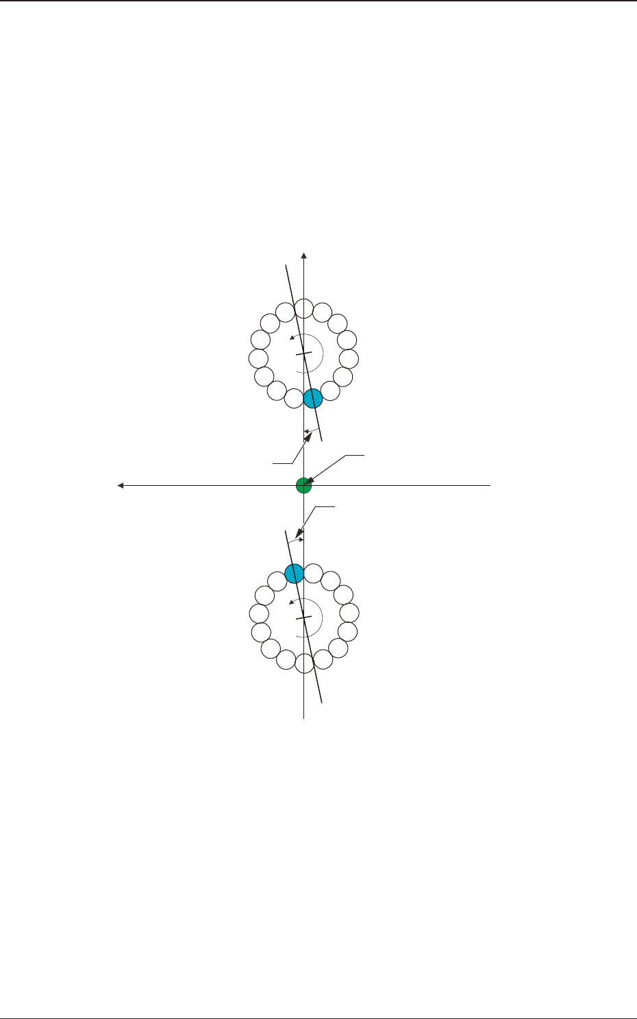
[4] Hd TumAng. Axis
The set parameters are used to adjust the angular deviation of the line
connecting the center of Nozzle No.1 and the position between the Nozzle
Nos. 8 and 9 at the head rotational Z-phase position based on the machine
coordinate reference.
When the line connecting the center of Nozzle No. 1 and the position
between the Nozzle Nos. 8 and 9 at the head rotational Z-phase position, is
tilted clockwise in the machine reference X/Y coordinate system, a plus sign
must be afxed to the offset value.
4
5
6
7
8
9
10
11
12
13
14
15
1
2
3
4
5
6
7
8
9
10
11
12
13
14
15
1
2
3
Xm(+)
Ym(+)
DD Motor Z-Phase
Stop Position
DD Motor Z-Phase
Stop Position
DD (+)
DD (+)
Head Rotational Angle Offset
Head Rotational Angle Offset
Pm. Machine Reference
Coordinate Origin
Xm-Ym :
Machine Reference
Coordinate System
F3B39
[5] NL Origin
The set parameters are used to correct the deviations between the nozzle U/D
mechanism and the nozzle roller caused while the NL axis is rotating.
[6] Noz Choice Axis
The set parameters are used to adjust the angular deviations between the
head rotational and nozzle selection axes.
[7] Flow Threshold
These parameters are used to judge the component presence/absence using
the multi-functional head ow sensor.
2.5 "Head" Window