3OM-1751-002w_G5S.pdf - 第193页
3OM-1751 2-25 1303-001 [4] [Ret] button When this button is pressed, the "Offset Data" window is returned. [5] [Save] button When this button is pressed, the input data is applied. [Cancel] button When this but…
3OM-1751
2-241303-001
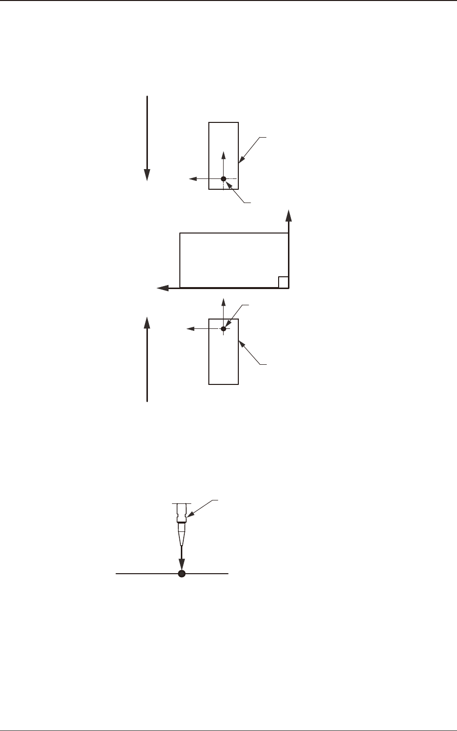
[2] X (Horizontal) and Y (Vertical) [mm]
These offset parameters are used to adjust the positional deviation based on
the design dimensions representing the component pickup position for each
individual feeder slot Nos. (Fdr Nos.).
F211
F111
Rear Feeder
Front Feeder
Front Side of Machine
Y(+)
X(+)
Pickup Position
Pickup Position
Direction of Tape Feed
Direction of Tape Feed
F3B24
[3] L (Height) [mm]
Pickup Reference Level
Nozzle
L(+)
F3B25
When a value is entered with a plus (+) sign, the pickup height is reected on
the direction in which the descending stroke of the nozzle will increase.
2.3 "Feeder A" and "Feeder B" Window

3OM-1751
2-251303-001
[4] [Ret] button
When this button is pressed, the "Offset Data" window is returned.
[5] [Save] button
When this button is pressed, the input data is applied.
[Cancel] button
When this button is pressed, the input data is cancelled and the save data is
returned.
2.3 "Feeder A" and "Feeder B" Window
3OM-1751
2-261303-001
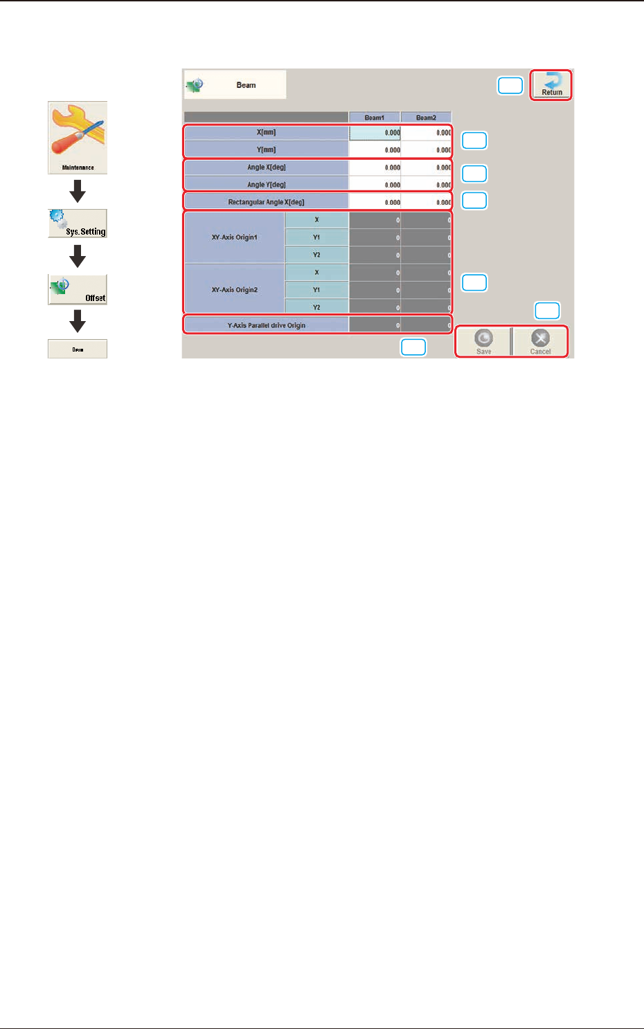
2.4 "Beam" Window
[1]
[2]
[3]
[6]
[7]
[4]
[5]
F3B26
[1] X (Horizontal) and Y (Vertical) [mm]
The set parameters are used to adjust the positional deviation based on the
design dimensions representing the distance between the machine reference
coordinate origin and the center of the PEC recognition camera at the head
origin.
2.4 "Beam" Window
Graphic
Development