3OM-1751-002w_G5S.pdf - 第170页
3OM-1751 2-2 2. "Offset Data" Window F3B2 Notice Do not change the parameters unless necessary . These parameters are factory-adjusted upon shipment of the machine. Graphic Development 1303-001 2. "Offset …
3OM-1751
2-11303-001
1. Menus for System Setting
[1]
F3B1
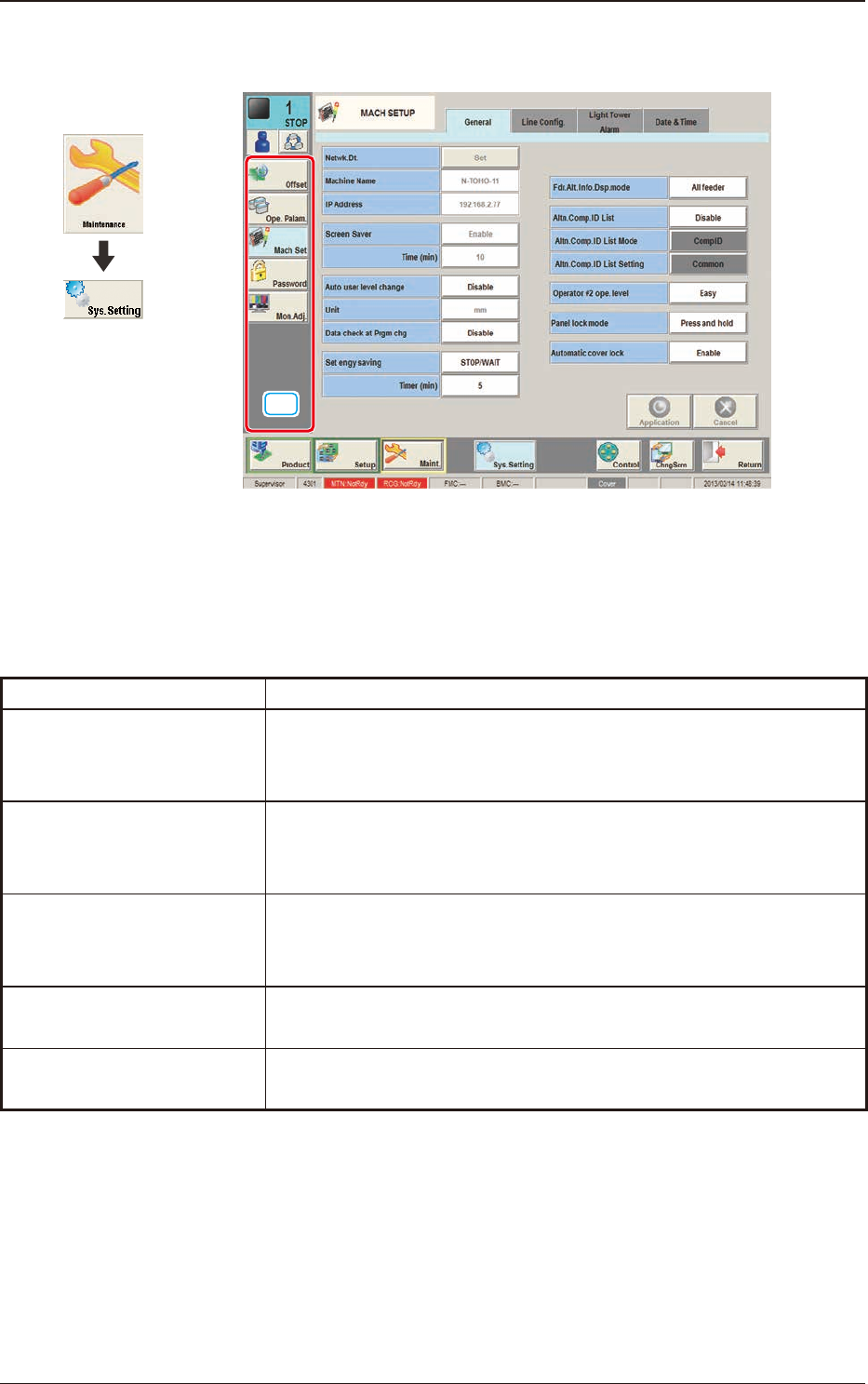
[1] "Sys. Setting" Main Menu Bar
The following buttons are arranged and used to open the operation windows
and set up the system environment.
Menu Buttons Description
Offset
The corresponding tab sheet enables the operator to set various kinds
of offset data for positional adjustment and accuracy of each device
section related to machine operation.
Ope. Palam.
The corresponding tab sheet enables the operator to set various
parameters related to automatic operation of the machine and check
the machine performance, production rate, production guidance, etc.
Mach Set
This enables the operator to set the screen saver function, specify the
unit of length, and enable or disable the data editing under production
operation.
Password
This enables the operator to set a password and the scope of authority
according to the given authority.
Mon. Adj.
This enables the operator to perform the monitor screen adjustment.
T3B1
Graphic
Development
1. Menus for System Setting
3OM-1751
2-2
2. "Offset Data" Window
F3B2
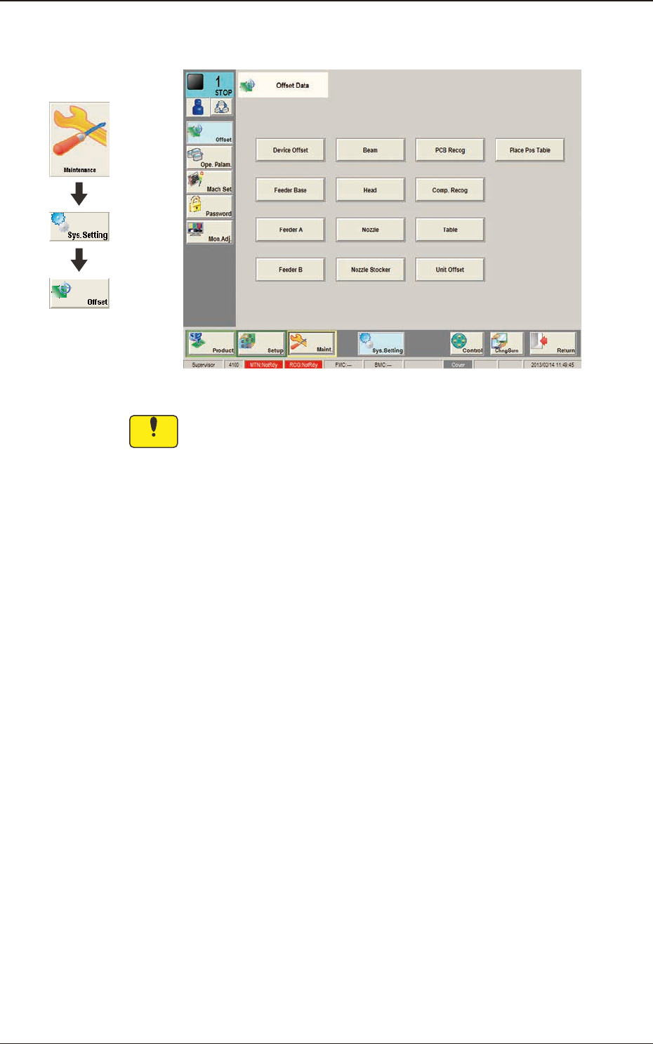
Notice
Do not change the parameters unless necessary. These
parameters are factory-adjusted upon shipment of the machine.
Graphic
Development
1303-001
2. "Offset Data" Window

3OM-1751
2-3
The "Offset Data" is provided with the following windows.
When each button is pressed, the corresponding window appears.
Tabs Description
Device Offset
The corresponding tab sheet enables the operator to adjust the positional and angular
deviations based on the design dimensions representing the X/Y beam driving X/Y
coordinates viewed from the PCB positioning X/Y coordinates.
Feeder Base
The corresponding tab sheet enables the operator to adjust the deviations based on the
design values of each individual feeders.
FeederA
This offset data is used independently for the machine. The corresponding tab
sheet enables the operator to adjust the positional deviations (viewed from the PCB
positioning X and Y coordinates) based on the design dimensions representing the
feeder pickup position and height for each individual feeder slot Nos. (Fdr Nos.).
FeederB
The corresponding tab sheet enables the operator to correct the variations, etc., for each
individual feeders.
Beam
The corresponding tab sheet enables the operator to correct the positional and angular
deviations based on the design dimension (the distance between the placement reference
coordinate origin and the center of the PEC recognition camera at the head origin).
Head
The corresponding tab sheet enables the operator to correct the positional deviation
(placement coordinates) caused due to the deviation of straightness (skew) of each
individual head up/down axis guides and set up the offset data for the distance between
the scanning coordinate center of the PEC camera and the head rotational center.
Nozzle
The corresponding tab sheet enables the operator to adjust the deviations in height
and rotational center of each nozzle and set the measured values of the master nozzle
(reference nozzle).
Nozzle Stocker
The corresponding tab sheet enables the operator to set the offset data for adjustment
(not available yet) of positional deviations compared with the design dimensions of the
nozzle stocker unit position (viewed from the PCB positioning reference) and the offset
data for adjustment of positional
deviations compared with the design dimensions (viewed from the PCB positioning
reference) for each individual addresses 1 through 15 of 1-1 to 2-2.
PCB Recog
The corresponding tab sheet enables the operator to adjust the horizontal swing (tilt) of
the PEC recognition camera.
Comp. Recog
The corresponding tab sheet enables the operator to set the offset data that will be used
to adjust the positional deviation based on the design dimension (the distance between
the machine reference coordinate origin and the center of the component recognition
camera).
Table
The corresponding tab sheet enables the operator to set the amount of deviation based
on the specied distance when each head (Heads 1 through 2) has moved as far as the
specied distance (each grid point) from the PCB positioning reference.
Unit Offset
The corresponding tab sheet is used when the multi-layer tray feeder is used.
Note
Refer to "Volume 7: Multi-Layer Tray Feeder" for details.
Place Pos Table
T3B2
1303-001
2. "Offset Data" Window