3OM-1751-002w_G5S.pdf - 第195页
3OM-1751 2-27 1303-001 [2] Angle X and Angle Y [deg] The set parameters are used to adjust the beam X and Y axes to the machine reference coordinate system. Xm(+) Ym(+) Yb(+) Xb(+) Yb(+) Xb(+) Head Origin Pm. Machine Ref…
3OM-1751
2-261303-001
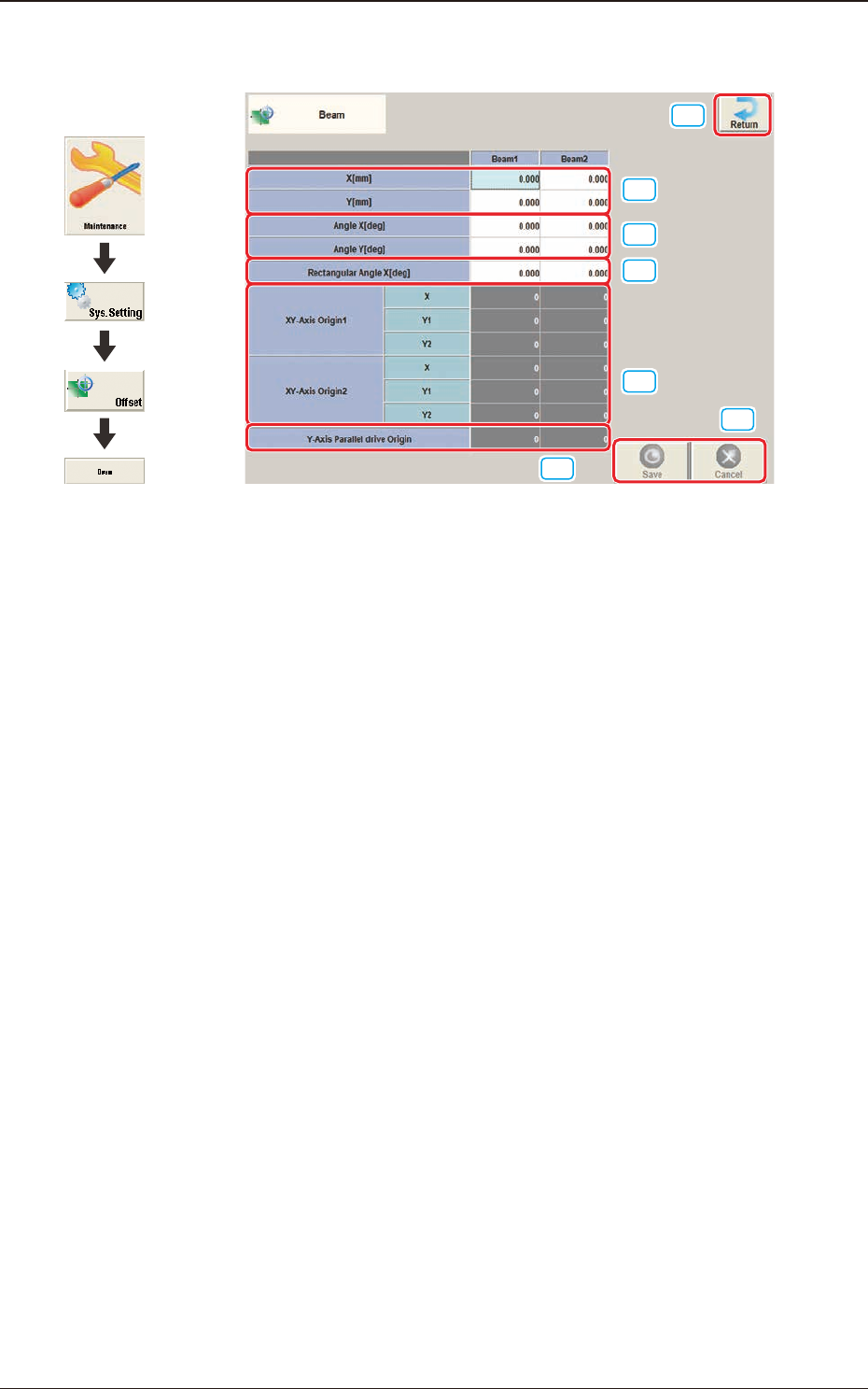
2.4 "Beam" Window
[1]
[2]
[3]
[6]
[7]
[4]
[5]
F3B26
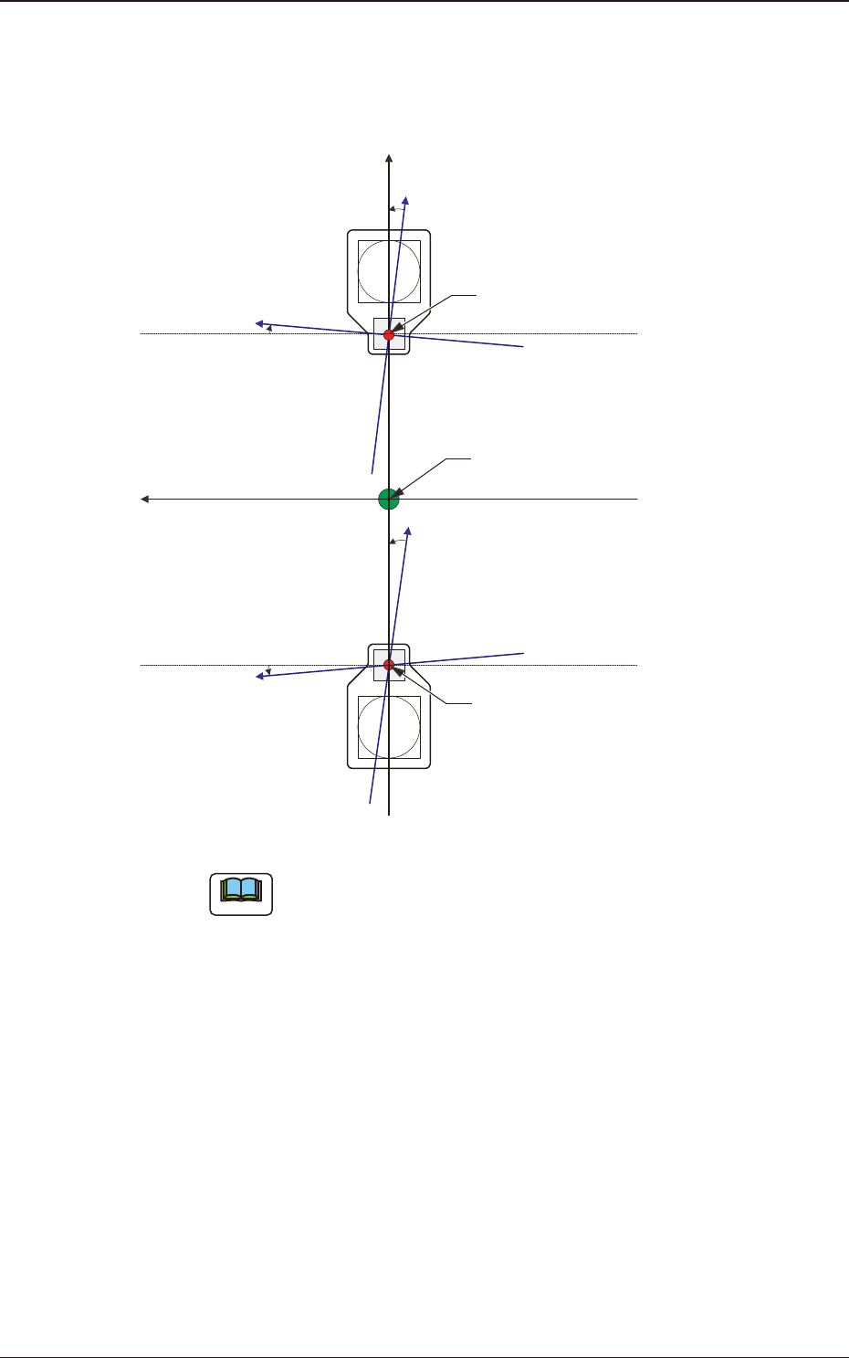
[1] X (Horizontal) and Y (Vertical) [mm]
The set parameters are used to adjust the positional deviation based on the
design dimensions representing the distance between the machine reference
coordinate origin and the center of the PEC recognition camera at the head
origin.
2.4 "Beam" Window
Graphic
Development
3OM-1751
2-271303-001
[2] Angle X and Angle Y [deg]
The set parameters are used to adjust the beam X and Y axes to the machine
reference coordinate system.
Xm(+)
Ym(+)
Yb(+)
Xb(+)
Yb(+)
Xb(+)
Head Origin
Pm. Machine Reference
Coordinate Origin
Head Origin
Xm-Ym
Xb-Yb
: Machine Reference
Coordinate System
: Real Beam Coordinate
System
F3B27
Note
A plus values must be entered in the "Angle X [deg]" and "Angle Y [deg]"
text boxes when the real beam coordinate system is tilted counterclockwise
(based on the machine reference coordinate system).
2.4 "Beam" Window
3OM-1751
2-281303-001
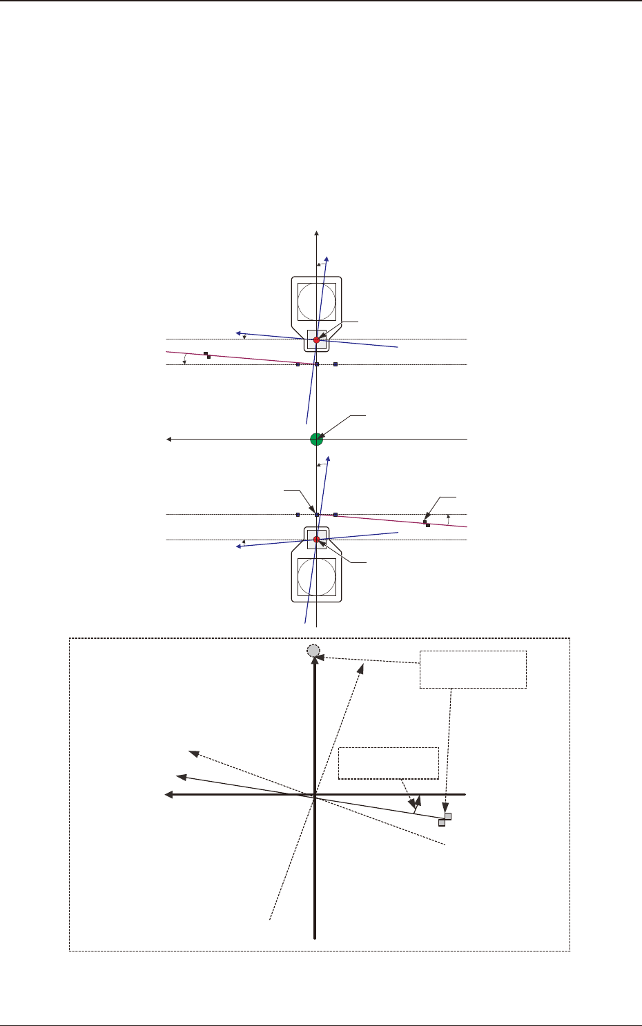
[3] Rectangular Angle X [deg]
These parameters represent the amount of angular deviations (X directions)
of the mark on the machine in comparison with the X directions in the
machine reference coordinate system.
The set parameters are used to check the three marks on the area of the
machine where only a little positional change can be made according to
temperature changes and adjust the beam X/Y axes such that they can cross
at right angles.
Xm(+)
Ym(+)
Yb(+)
Xb(+)
Yb(+)
Xb(+)
Xm'
Machine Reference
Coordinate System
Mark Coordinate
System
Beam Coordinate
System
Mark on Machine
Rectangular Angle
X [deg]
Head Origin
Pm. Machine Reference
Coordinate Origin
Standard Mark 2
Head Origin
Standard Mark 1
Xm-Ym
Xb-Yb
: Machine Reference
Coordinate System
: Real Beam Coordinate
System
F3B28
2.4 "Beam" Window