3OM-1751-002w_G5S.pdf - 第242页
3OM-1751 2-74 1303-001 · Set-up 1 [1] [2] [3] [4] [5] [6] F3B73 [1] Auto fdr axis adj. set picks [times] Set the total number of collected samples when data is updated or changed. (X) adj. [%] Set the feedback coefcient…
3OM-1751
2-731303-001
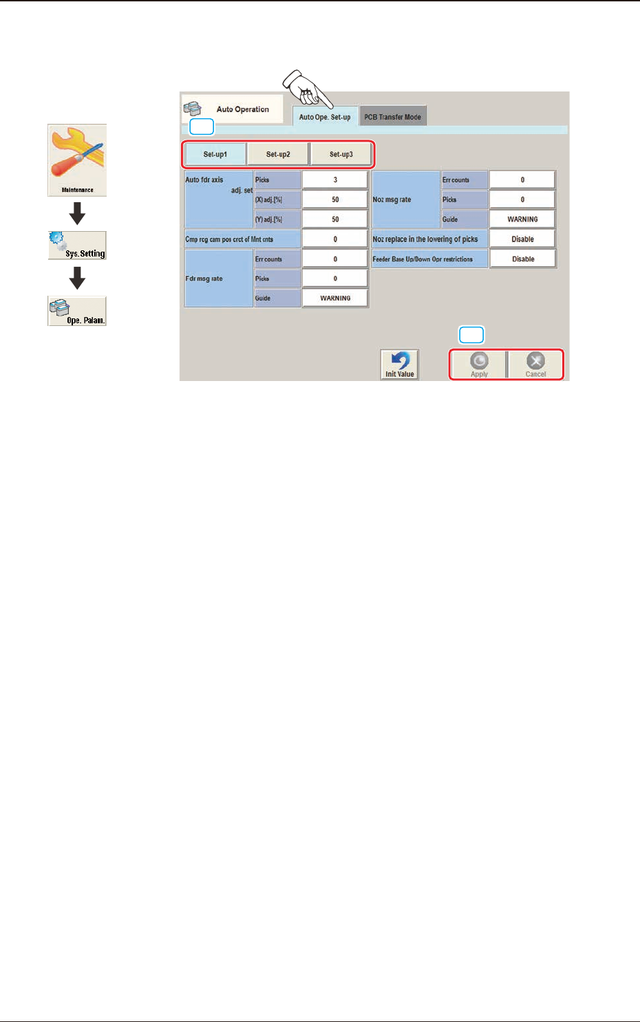
3.1 "Auto Ope. Set-up" Tab Sheet
[1]
[2]
F3B72
[1] Set-up Change Button
When press the window is changed over from "Set-up 1", "Set-up 2" and
"Set-up 3" or vice versa.
[2] [Apply] button
When this button is pressed, the input data is applied.
[Cancel] button
When this button is pressed, the input data is cancelled and the save data is
returned.
3.1 "Auto Ope. Set-up" Tab Sheet
Graphic
Development
3OM-1751
2-741303-001
·
Set-up 1
[1]
[2]
[3]
[4]
[5]
[6]
F3B73
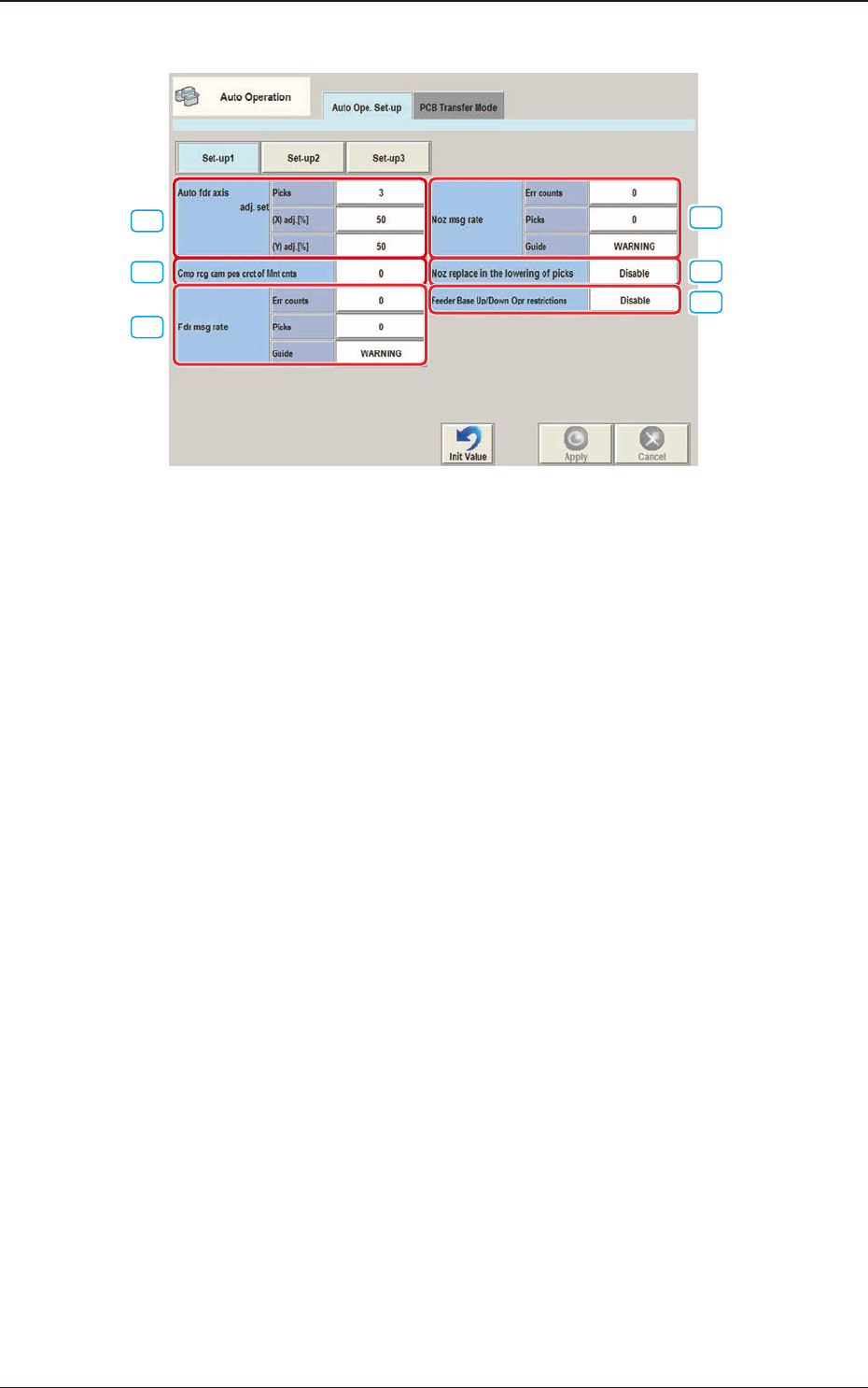
[1] Auto fdr axis adj. set
picks [times]
Set the total number of collected samples when data is updated or changed.
(X) adj. [%]
Set the feedback coefcient of the mean of the X-direction deviation in this
data box.
Set Value Range: 10 to 90
(Y) adj. [%]
Set the feedback coefcient of the mean of the Y-direction deviation in this
data box.
Set Value Range: 10 to 90
3.1 "Auto Ope. Set-up" Tab Sheet
3OM-1751
2-751303-001
[2] Cmp rcg cam pos crct of Mnt cnts [times]
Press the value to display the "Ten-key Input" window and enter one of the
following values.
"0"
: No automatic correction operation is performed for
each number of components to be placed.
"1" to "9999"
: Correction is made according to the specied number
of components to be placed.
Note
(a) When "Correct" is set in the "Mode" text box, the corrective actions
take place automatically before the PCB is transferred to the PCB
positioning section and the component recognition operation is
performed.
(b) When the number of components (components to be placed on
a production PCB) per beam is smaller than the set number of
components, the corrective actions do not take place in the middle of
placement operation.
Because the internal counter for interval monitoring is cleared
through the above-described corrective actions (the actions which
take place during PCB positioning), no corrective actions take place
in compliance with the number of components to be placed on several
PCBs.
[3] Fdr msg rate
Err count [times], pick [times]
Set the parameters to show the feeder slot No. (Fdr. No.) of the tape feeder
whose pickup rate has deteriorated during automatic operation.
When the number of picks has reached the specied value, the parameter in
the "Error counts" text box is cleared.
Note
The number of picks and pick-up errors is managed for each individual
feeders but the parameters of "Error counts" and "# of picks" is equally
reected on every feeder.
Guide
"WARNING", "Stop (Cycle stop), or "Pause" can be selected to determine
in which mode the machine should be set when the number of pickup errors
has reached the specied error counts before the number of picks reaches the
specied number of picks. When "Warning" is selected, a warning message
is issued as machine information. "Stop (Cycle stop)" stops the machine after
one cycle of operation and "Pause" sets the machine in the "PAUSE" mode.
Note
When both "Error counts" and "# of picks" are set "0" (zero) or "Error
counts" is set to a number larger than "# of picks", no warning message is
issued.
3.1 "Auto Ope. Set-up" Tab Sheet