3OM-1751-002w_G5S.pdf - 第249页
3OM-1751 2-81 1303-001 3.2 "PCB T ransfer Mode" T ab Sheet [3] [4] [1] [2] F3B76 · Set-up 1 [1] Auto transfer mode Whether or not the automatic transfer mode in the PCB discharge operation is used, is set in th…

3OM-1751
2-80
[4] Vibration control
Mode
The machine vibration is controlled by means of setting the deceleration in
the beam operation in the Y-direction.
Rate [%]
Set the vibration control rate in this data box.
Set Value Range: 1 to 99
[5] Trash box ll up Notice warning
For the Trash box ll-up notice warning, the following items are set.
Function
"Enable" or "Disable" is set in this selection box.
Notice [×1000]
Count : 1 to 9999 [×1000]
Initial value : 900 [×1000]
[6] Trash box ll up Stop warning
For the Trash box ll-up stop warning, the following items are set.
Function
"Enable" or "Disable" is set in this selection box.
Stop [×1000]
Count : 1 to 9999 [×1000]
Initial value : 1350 [×1000]
[7] Cmput box ll up Notice warning
The component discharge box full count is set in this data box.
1303-001
3.1 "Auto Ope. Set-up" Tab Sheet
3OM-1751
2-811303-001
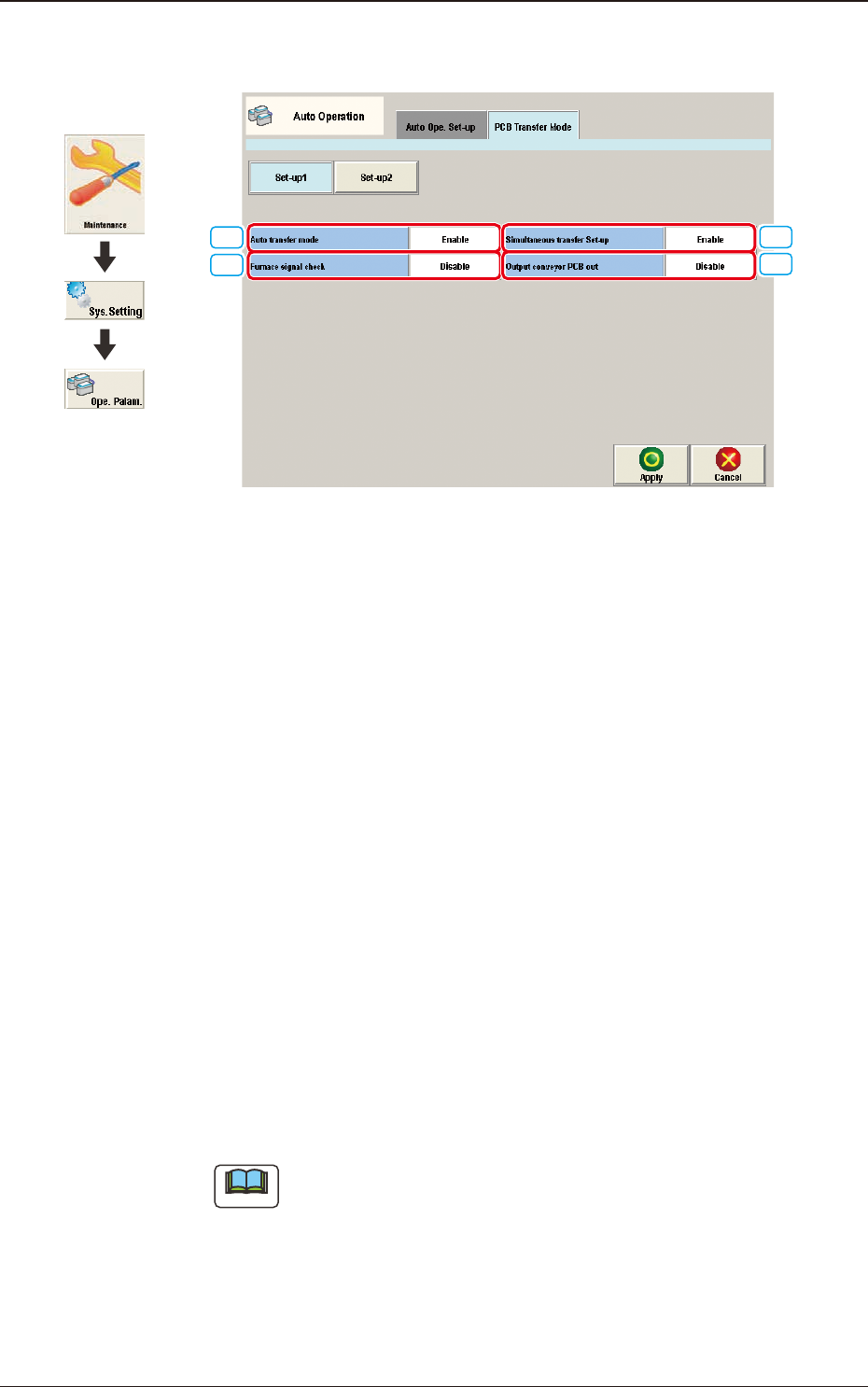
3.2 "PCB Transfer Mode" Tab Sheet
[3]
[4]
[1]
[2]
F3B76
·
Set-up 1
[1] Auto transfer mode
Whether or not the automatic transfer mode in the PCB discharge operation
is used, is set in this selection box.
Enable
The discharge of the PCB where the components have been placed, on the
PCB positioning unit, is performed at the same time of the transfer of the
next PCB to the PCB positioning unit.
Disable
The discharge of the PCB (nished PCB) to the output machine is performed
in this PCB transfer mode, when the components have been placed on the
PCB on the PCB positioning unit and there is no PCB on the buffer section
and the conveyor movement is not started.
[2] Furnace signal check
Set "Disable" or Enable" to determine whether or not the furnace signal
check function should be activated.
Note
When "SMEMA" is set in the "Input mode" text box of the label "Input
Setup" or in the "Output mode" text box of the label "Output Setup", this
function cannot be used.
3.2 "PCB Transfer Mode" Tab Sheet
Graphic
Development

3OM-1751
2-821303-001
[3] Simultaneous transfer Set-up
Select "Enable" or "Disable" to determine whether or not the PCB transfer
should be made simultaneously between the input and positioning conveyors
and between the positioning and output conveyors.
[4] Output conveyor PCB out
Set "Disable" or "Enable" to determine whether or not a disengaged PCB
should be detected in the output conveyor section.
3.2 "PCB Transfer Mode" Tab Sheet