3OM-1751-002w_G5S.pdf - 第175页
3OM-1751 2-7 1303-001 2.1.3 "Pos Level" T ab Sheet [1] F3B6 [1] BL [mm] BR [mm] These parameters are used to absorb the deviation in the PCB positioning level for the Support pin up/down operation. Graphic Deve…
3OM-1751
2-61303-001
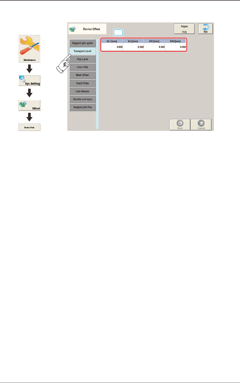
2.1.2 "Transport Level" Tab Sheet
[1]
F3B5
[1] BL1 [mm]
BL2 [mm]
BR1 [mm]
BR2 [mm]
Each parameters are used to correct the positional deviations in PCB transfer
positioning in comparison with Support pin up/down operation.
Graphic
Development
2.1 "Device Offset" Window
3OM-1751
2-71303-001
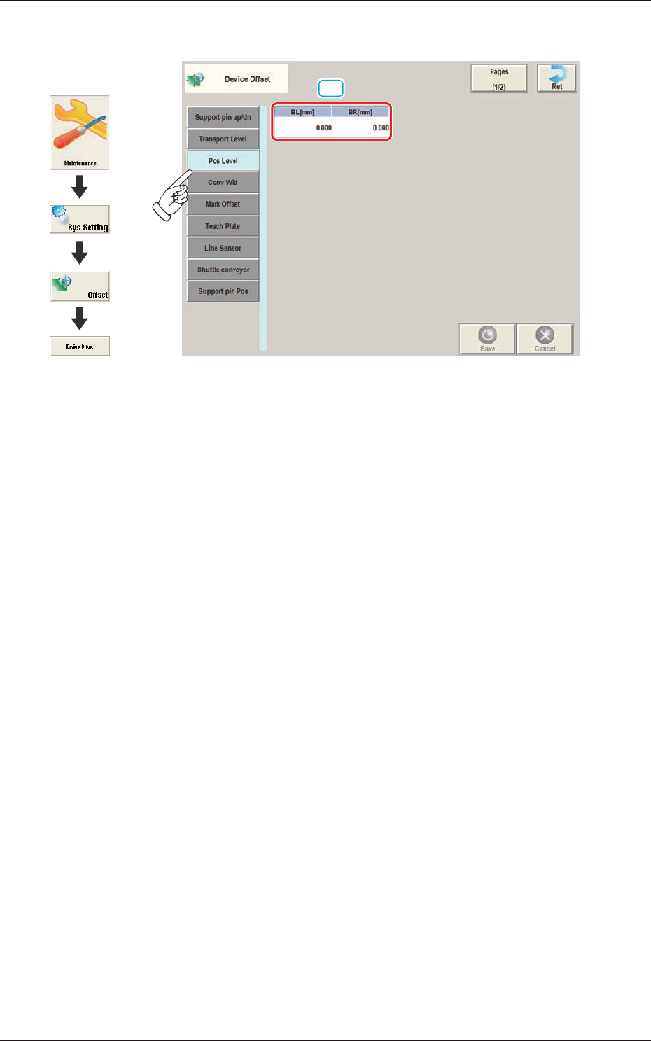
2.1.3 "Pos Level" Tab Sheet
[1]
F3B6
[1] BL [mm]
BR [mm]
These parameters are used to absorb the deviation in the PCB positioning
level for the Support pin up/down operation.
Graphic
Development
2.1 "Device Offset" Window
3OM-1751
2-81303-001
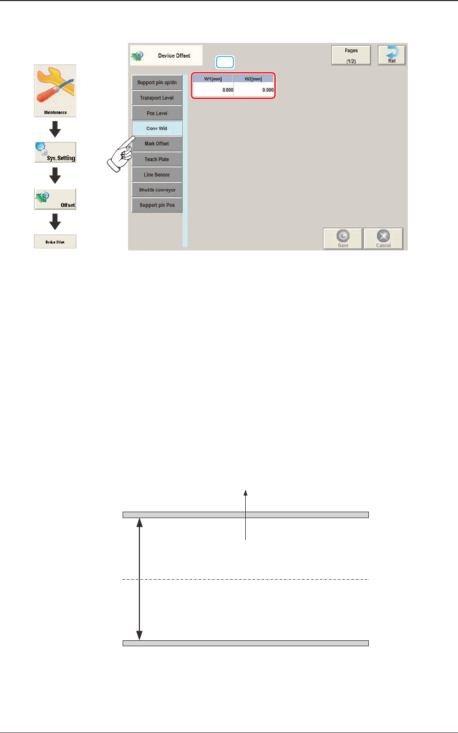
2.1.4 "Conv Wid" Tab Sheet
[1]
F3B7
[1] W1 [mm]
W2 [mm]
This offset data is used to adjust the conveyor width to the absolute values. Enter
the difference between the actually measured value from the xed chute to the
movable chute and the half of the specied width, when the conveyor width is set
up to the specied one.
W1 Offset
: In the case that the actually measured value is larger than half of the
specied one, a positive (+) value must be entered.
W2 Offset
: In the case that the actually measured value is smaller than half of
the specied one, a negative (-) value must be entered.
A
NL-W1
NR-W1
NB-W1
NL-W2
NR-W2
NB-W2
(+)
(-)
Front Side of Machine
Movable Chute
Fixed Chute
F3B8
Graphic
Development
2.1 "Device Offset" Window