3OM-1751-002w_G5S.pdf - 第251页
3OM-1751 2-83 1303-001 · Set-up 2 [1] [2] [3] [4] [5] [6] [7] [8] [9] [10] [11] F3B77 [1] Input mode Select a parameter according to the PCB unloading system of the input machine. Conveyor The input machine is activated …

3OM-1751
2-821303-001
[3] Simultaneous transfer Set-up
Select "Enable" or "Disable" to determine whether or not the PCB transfer
should be made simultaneously between the input and positioning conveyors
and between the positioning and output conveyors.
[4] Output conveyor PCB out
Set "Disable" or "Enable" to determine whether or not a disengaged PCB
should be detected in the output conveyor section.
3.2 "PCB Transfer Mode" Tab Sheet
3OM-1751
2-831303-001
·
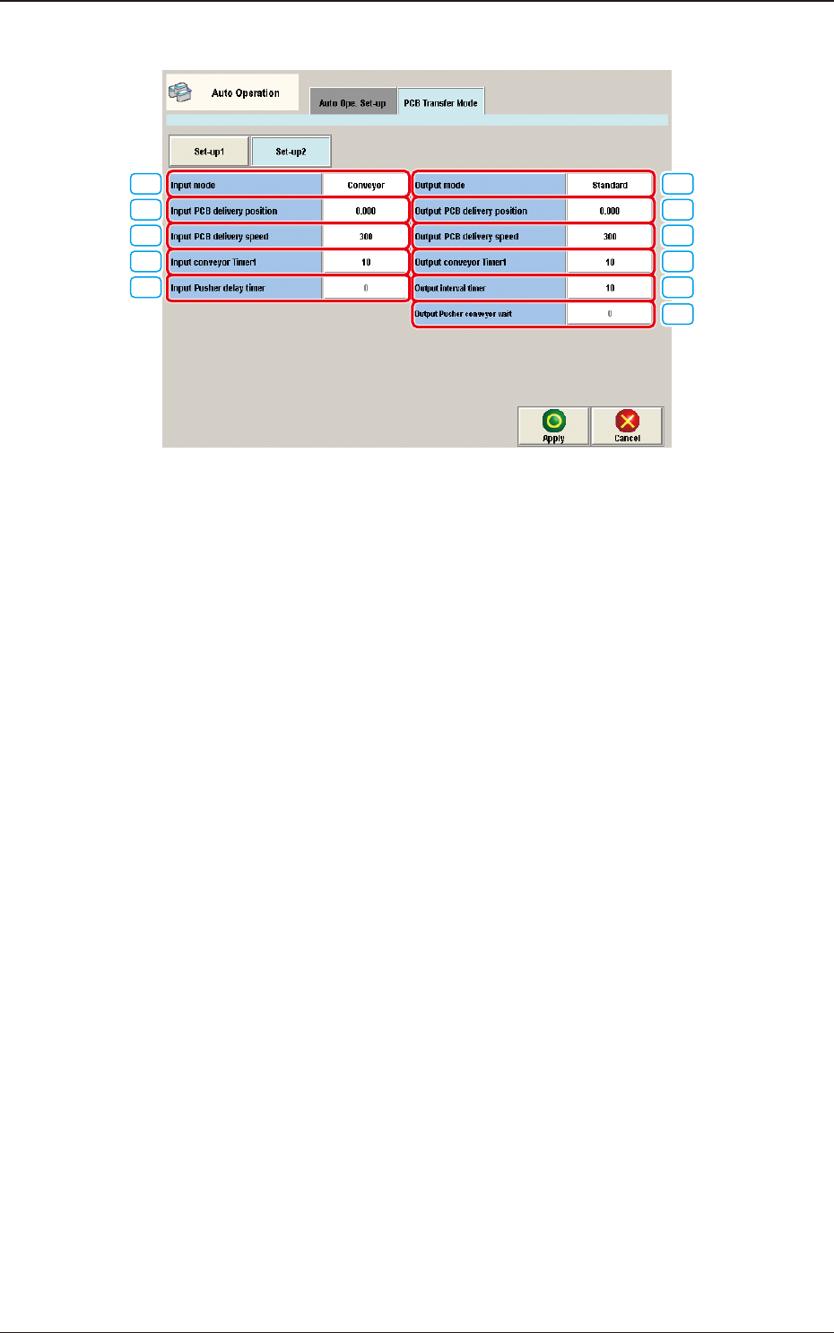
Set-up 2
[1]
[2]
[3]
[4]
[5]
[6]
[7]
[8]
[9]
[10]
[11]
F3B77
[1] Input mode
Select a parameter according to the PCB unloading system of the input
machine.
Conveyor
The input machine is activated to receive a PCB from the input machine
when the PCB transfer signal is received from the input machine.
Pusher
The pusher of the input machine forces a PCB out to the input conveyor of
the machine.
When the PCB detection sensor (for the pusher) is not provided at the inlet
side of the input conveyor, do not set "Pusher" in the text box.
SMEMA
PCBs are transferred according to the "SMEMA" standard.
[2] Input PCB delivery position [mm]
Set the PCB delivery position.
[3] Input PCB delivery speed [mm/sec]
Set the PCB delivery speed.
•
Default
: 300 [mm/sec]
3.2 "PCB Transfer Mode" Tab Sheet
3OM-1751
2-841303-001
[4] Input conveyor Timer1 [sec]
Set the time to limit the operating time (PCB reception from the input
machine) of the input conveyor.
This timer measures the operating time of the input conveyor and is used to
detect an interrupted PCB.
Note
Add 2 seconds (approx.) to the time required for PCB reception from the
input machine and set the time in the text box.
[5] Input Pusher delay timer [sec]
When "Pusher" is set in the "Input mode" text box of the label "Input Setup",
it is required to specify the delay (waiting) time for the loading action to start
after the inlet sensor has detected a PCB.
[6] Output mode
The PCB delivery to the output machine is set in this section.
Standard
When the output machine is manufactured by us, set "Standard" in the
text box.
When the work request signal is received from the output machine, the
PCB transfer signal of the machine is turned ON and a PCB is transferred
to the output machine by the output conveyor.
When the work request signal is not turned OFF within the specied time
after a PCB unloading action has started, the machine stops in an error
condition.
Interval
When the work request signal of the output machine is turned ON, PCBs
on the machine side are transferred to the output machine.
The conveyor stops when the output conveyor timer 1 has reached the
specied time.
The machine starts its unloading actions when the unloading condition is
fullled after the conveyor has stopped running and the time specied in
the "Output interval timer [sec]" text box has elapsed.
Note
No error detection is made.
SMEMA
PCBs are transferred according to the "SMEMA" standard.
3.2 "PCB Transfer Mode" Tab Sheet