3OM-1751-002w_G5S.pdf - 第189页
3OM-1751 2-21 1303-001 2.1 "Device Offset" Window 2.1.16 "Backup Base Standby Pos" T ab Sheet [1] F3B21 Graphic Development
3OM-1751
2-201303-001
2.1 "Device Offset" Window
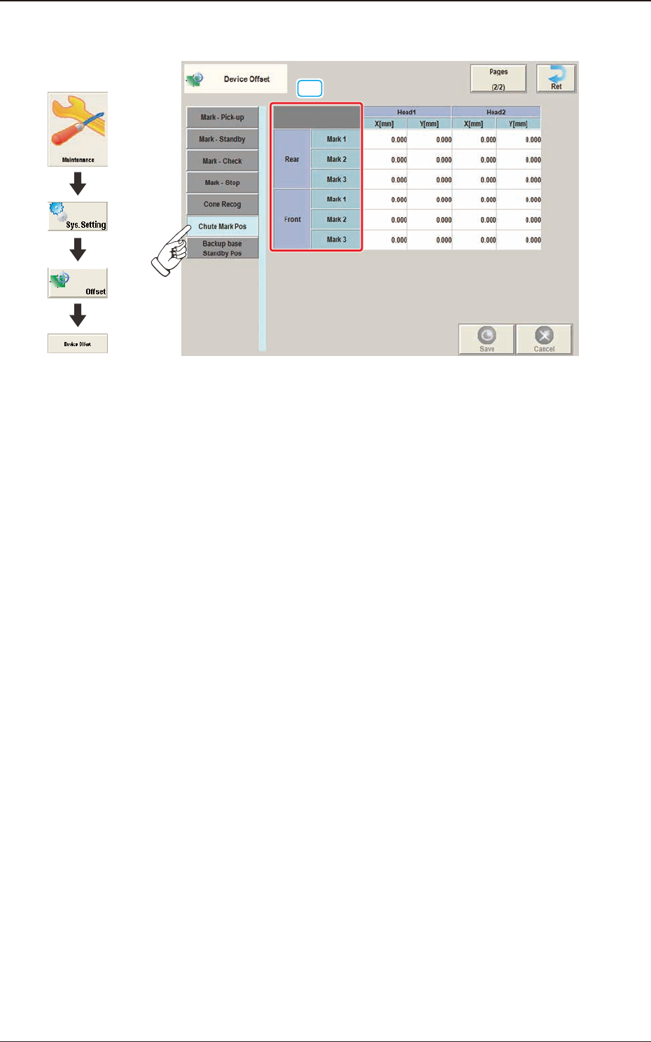
2.1.15 "Chute Mark Pos" Tab Sheet
[1]
F3B20
Graphic
Development
3OM-1751
2-211303-001
2.1 "Device Offset" Window
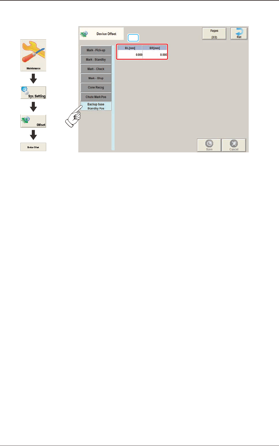
2.1.16 "Backup Base Standby Pos" Tab Sheet
[1]
F3B21
Graphic
Development
3OM-1751
2-221303-001
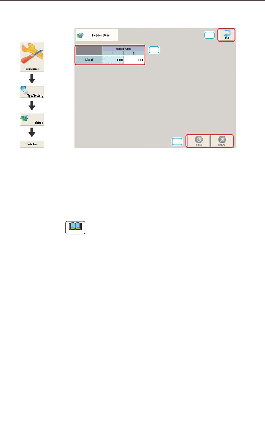
2.2 "Feeder Base" Window
[1]
[2]
[3]
F3B22
[1] L [mm]
The set offset parameters are used to adjust the positional deviations (height
direction) based on the design dimensions of Feeder Bases #1 and #2.
When the feeder bases are installed lower than the design values, a plus
value must be entered in each text box.
Note
The tilts of the PCB positioning sections on the feeder base sections are
calculated on the X and Y values of "Mark (Left)" and "Mark (Right)"
[2] [Ret] button
When this button is pressed, the "Offset Data" window is returned.
[3] [Save] button
When this button is pressed, the input data is applied.
[Cancel] button
When this button is pressed, the input data is cancelled and the save data is
returned.
2.2 "Feeder Base" Window
Graphic
Development