00198442-01_UM_TX-V2_EN.pdf - 第117页
User manual SIPLACE TX V2 3 Technical data and assemblies From software version 711.1 04/2018 3.5 Placement head 117 3.5.4.3 Placement modes for MultiS t ar The CPP head functions with dif f erent placement m odes, which…

3 Technical data and assemblies User manual SIPLACE TX V2
3.5 Placement head From software version 711.1 04/2018
116
3.5.4.1 Assembly positions of SIPLACE MultiStar
The CPP head can be fitted to the head mount in two different positions:
– MultiStar in the top assembly position
In this position, all components can be processed up to a size of 50 mm x 40 mm and a height
of 11.5 mm. 3
– MultiStar in the bottom assembly position
In this position, the CPP head places components up to a size of
27 mm x 27 mm and a component height of 6 mm for the SIPLACE TX1/TX2 and 4 mm for
the SIPLACE TX2i, using the Collect&Place method. 3
Observe the following rules when defining the assembly position:
The head height must be the same for all heads in the same placement area.
Always install the CPP head in the top assembly position if it is to be combined with the fol-
lowing assemblies:
– Stationary component camera
–TwinStar
3.5.4.2 Classification of component range to be processed
3
Component
class
Component
size
Assembly
position
*a
of CPP
head
Component
height
Component
camera type
Small compo-
nent
K_BE
01005 to 15 mm
x 15 mm
Top Up to 8.5 mm
Head camera,
type 45
Bottom Up to 6.0 mm
Small compo-
nent
K_BE
01005 to 27 mm
x 27 mm
Top Up to 8.5 mm
Head camera,
type 30
Bottom Up to 6.0 mm
Medium sized
component, type
M_BE_1
< 27 x 27 mm
Top
Between 8.5 and
11.5 mm
Stationary compo-
nent camera,
type 33
Bottom Not possible
Medium sized
component, type
M_BE_2
Between
27 mm x 27 mm
and
32 mm x 32 mm
Top 11.5 mm
Bottom Not possible
Large compo-
nent
G_BE
Between
32 mm x 32 mm
and
50 mm x 40 mm
Top Up to 11.5 mm
Stationary compo-
nent camera,
type 33
Bottom Not possible
Tab. 3.5 - 1Classification of component range to be processed
*)a Please observe the rules for assembly position heights in section 3.5.4.1
, page 116.

User manual SIPLACE TX V2 3 Technical data and assemblies
From software version 711.1 04/2018 3.5 Placement head
117
3.5.4.3 Placement modes for MultiStar
The CPP head functions with different placement modes, which vary according to the component
class. The setup optimization selects the placement mode with the shortest cycle times. The fol-
lowing table shows the correlation between component class and placement mode.
Tab. 3.5 - 2 Relations between component class and placement modes
3.5.4.4 assembly positions of SIPLACE MultiStar
Placement mode Component class
Small component Medium sized
component
Large component
Collect&Place mode Yes No No
Mixed mode Yes Yes No
Advanced
Pick&Place mode
Yes Yes Yes
Placement machine Assembly
position
*a
CPP head
Maximum component
height
Vision camera
SIPLACE TX1/2 Bottom 6.0 mm Head camera
Top 8.5 mm Head camera
Top only 11.5 mm
Stationary component
camera
SIPLACE TX2i Bottom 4,0 mm Head camera
Tab. 3.5 - 3Assembly positions of CPP head in the placement machine
*)a Please observe the rules for assembly position heights in section 3.5.4.1
, page 116.
3 Technical data and assemblies User manual SIPLACE TX V2
3.5 Placement head From software version 711.1 04/2018
118
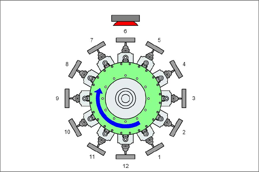
3.5.4.5 MultiStar in Collect&Place mode
The MultiStar does not process components in this mode.
3
Fig. 3.5 - 7 MultiStar - Collect&Place mode
K_BE Small component (see table 3.5 - 1, page 116)
Type 30 Component camera, type 30
1 ... 12 Order of components taken up
3
Type 30
K_BE