00198442-01_UM_TX-V2_EN.pdf - 第122页
3 Technical data and assemblies User manual SIPLACE TX V2 3.5 Placement head From software version 711.1 04/2018 122 3.5.5 SIPLACE T winSt ar for high precision IC placement 3 Fig. 3.5 - 10 SIPLACE T winStar for high pre…
User manual SIPLACE TX V2 3 Technical data and assemblies
From software version 711.1 04/2018 3.5 Placement head
121
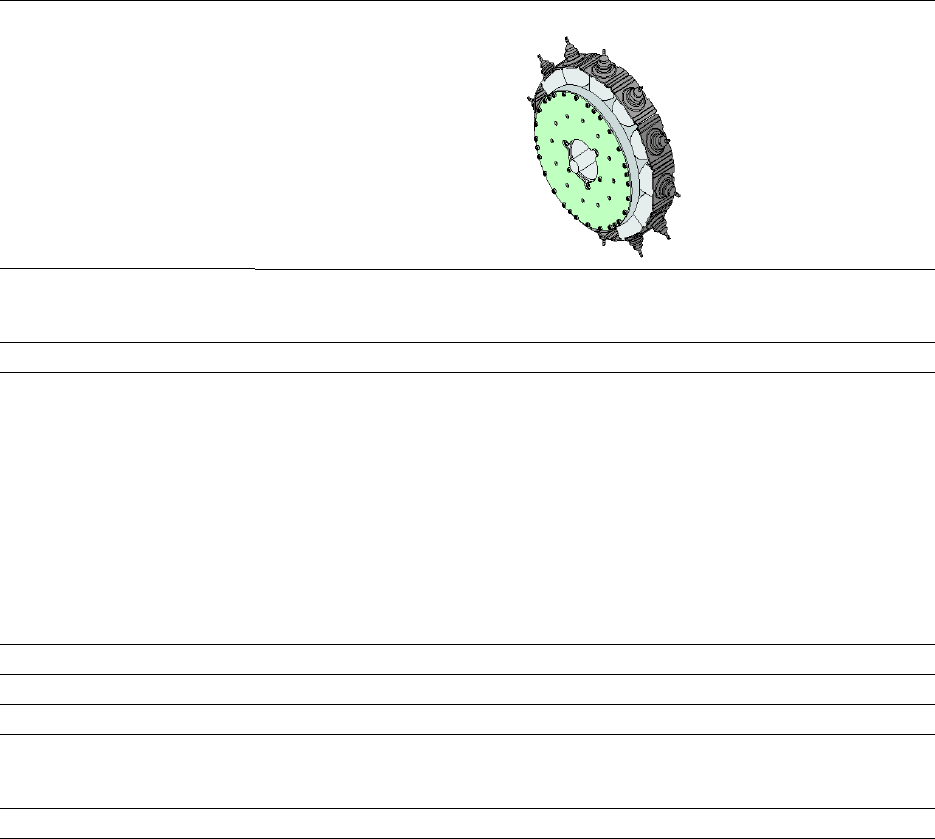
3.5.4.8 Technical data for SIPLACE MultiStar (CPP) on SIPLACE TX
3
SIPLACE MultiStar (CPP)
with component camera
type 30
With component camera
type 45
with component camera
type 33
(stationary camera)
Component range
*a
01005 to 27 mm x 27 mm 01005 to 15 mm x 15 mm 0402 to 50 mm x 40 mm
*b
Component spec.
Max height
*c
Max. height
*d
Min. lead pitch
Min. lead width
Min. ball pitch
Min. ball diameter
Min. dimensions
Max. dimensions
Max. weight
4.0 mm
*e
/ 6.0 mm
8.5 mm
250 µm
100 µm
*f
/ 200 µm
*g
250 µm
e
/ 350 µm
140 µm
e
/ 200 µm
f
0.4 mm x 0.2 mm
27 mm x 27 mm
4 g
6.0 mm
8.5 mm
250 µm / 120 µm
*h
50 µm
140 µm
70 µm
0.11 mm x 0.11 mm
15 mm x 15 mm
4 g
11.5 mm
300 µm
150 µm
350 µm
200 µm
1.0 mm x 0.5 mm
50 mm x 40 mm
8 g
Programmable set-down force 1.0 - 10 N
Nozzle types 20xx, 28xx 20xx, 28xx 20xx, 28xx
X/Y accuracy
*i
± 40 µm/3σ ± 40 µm/3σ ± 34 µm/3σ
Angular accuracy ± 0.20° / 3σ
*j
, ± 0.38° /
3σ
*k
± 0.25° / 4σ
h
, ± 0.50° / 4σ
i
± 0.38° / 3σ ± 0.14° / 3σ
± 0.18° / 4σ
Illumination level 5 5 6
*)a Please note that the placeable component range is also affected by the pad geometry, the customer-specific standards,
the component packaging tolerances and the component tolerances.
*)b A diagonal of 69 mm is possible during multiple measurements (e.g. 64 mm x 10 mm).
*)c CPP head: in low installation position (stationary component camera not possible).
*)d CPP head: in high installation position
*)e Only 4 mm possible for SIPLACE TX2i.
*)f For components < 18 mm x 18 mm
*)g For components ≥ 18 mm x18 mm
*)h Only possible for components which are within the camera focal area of ± 1.3 mm.
*)i The accuracy values fulfill the conditions in the SIPLACE scope of supply and services.
*)j Component dimensions between 6 mm x 6 mm and 27 mm x 27 mm.
*)k Component dimensions smaller than 6 mm x 6 mm.
3 Technical data and assemblies User manual SIPLACE TX V2
3.5 Placement head From software version 711.1 04/2018
122
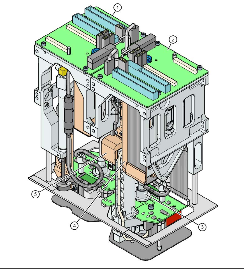
3.5.5 SIPLACE TwinStar for high precision IC placement
3
Fig. 3.5 - 10 SIPLACE TwinStar for high precision IC placement
3
(1) Pick&Place module 1 (P&P1)
(2) Pick&Place module 2 (P&P2)
(3) DP axis
(4) Z axis drive
(5) Incremental distance measuring system for the Z axis
User manual SIPLACE TX V2 3 Technical data and assemblies
From software version 711.1 04/2018 3.5 Placement head
123
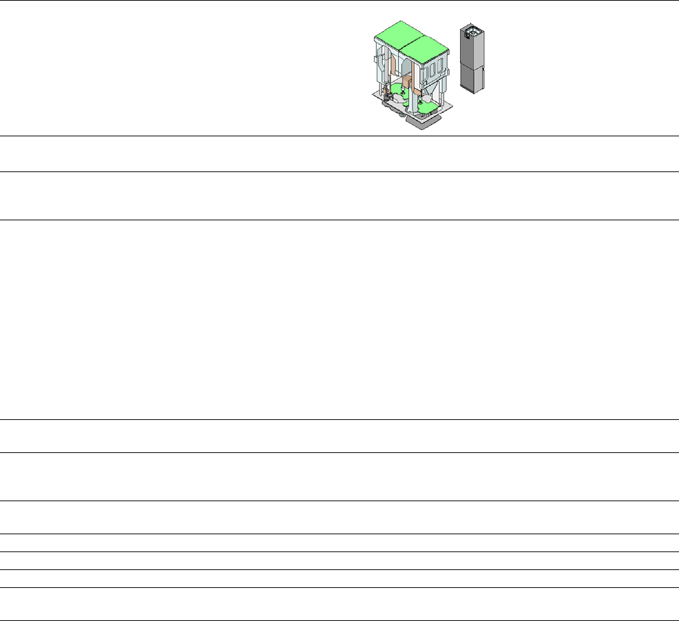
3.5.5.1 Technical data Twin Star
SIPLACE TwinStar
with component camera type 33
(fine pitch camera)
with component camera type 25
(flip chip camera)
Component range
*a
0402 to SO, PLCC, QFP, BGA, special
components, bare dies, flip-chips
0201 to SO, PLCC, QFP, sockets, plugs, BGA,
special components, bare dies, flip-chips,
shields
Component specs
Max. height
Min. lead pitch
Min. lead width
Min. ball pitch
Min. ball diameter
Min. dimensions
Max. dimensions
Max. weight
*b
25 mm
300 µm
150 µm
350 µm
200 µm
1.0 mm x 0.5 mm
55 mm x 45 mm (single measurement)
75 mm x 10 mm (multiple measure-
ment)
100 g
25 mm
250 µm
100 µm
140 µm
80 µm
0.6 mm x 0.3 mm
16 mm x 16 mm (single measurement)
100 g
Programmable set-down
force
1.0 N - 15 N 1.0 N - 15 N
Nozzle types 5xx (standard)
20xx / 28xx (with nozzle adapter 20xx/28xx on 5xx)
Special nozzles, gripper
Nozzle spacing for P&P
heads
70.8 mm 70.8 mm
X/Y accuracy
*c
± 28 µm/3σ ± 22 µm/3σ
Angular accuracy ± 0.05° / 3σ ± 0.05° / 3σ
Illumination level 6 6
Possible illumination level
settings
256
6
256
6
*)a Please note that the placeable component range is also affected by the pad geometry, the customer-specific standards, the
component packaging tolerances and the component tolerances.
*)b Component plus nozzle or gripper.
*)c The accuracy values fulfill the conditions in the SIPLACE scope of supply and services.