00198442-01_UM_TX-V2_EN.pdf - 第147页
User manual SIPLACE TX V2 3 Technical data and assemblies From software version 711.1 04/2018 3.9 Component trolley 147 3.9 Component trolley T w o SIPLACE TX component trolle ys can be docked onto SIPL ACE TX placement …
3 Technical data and assemblies User manual SIPLACE TX V2
3.8 SIPLACE tape feeder modules for SIPLACE TX From software version 711.1 04/2018
146
3.8.4.1 Description
The energy and data interface allows X feeder modules to be used outside the placement machine
and presetup area. The interface consists of an aluminum frame with omega profile for holding
and guiding the feeder modules. As with the component trolley, the feeder module is placed on
the omega profile, with the slider guides, and is pushed forwards until the front centering pin of the
feeder module is fully inserted into the locating hole. The locking latch locks the feeder module in
this position. To remove the feeder module, simply press the release button. The locking latch is
pressed downwards and releases the feeder module. Fold-out feet stabilize the position of the en-
ergy and data interface, particularly for wider feeder modules.
The electronics housing holds the electronic control unit for the energy and data interface. The
operating panel consists of start and stop buttons and two status LEDs. Communication with a PC
takes place via the data cable. The power supply cable is connected to the power supply unit pro-
vided.
3.8.4.2 Usage
The energy and data interface is used to check, maintain and repair X feeder modules. It can also
be used for setting up in advance for PCB production. In this case, the energy and data interface
is fixed to the base plate. The tape reel holder is also mounted on the base plate. When a com-
ponent tape is inserted, you can check or reset the increment, pick-up position and conveyor
speed. The detailed user manual describes how to use the interface and the necessary servicing
work.
3.8.4.3 Scope of delivery
– Single Slot EDIF
– Power supply, 100 - 120 / 200 - 240 VAC, +30VDC, 4.3 A
– Base plate with tape reel arm
– User manual
User manual SIPLACE TX V2 3 Technical data and assemblies
From software version 711.1 04/2018 3.9 Component trolley
147
3.9 Component trolley
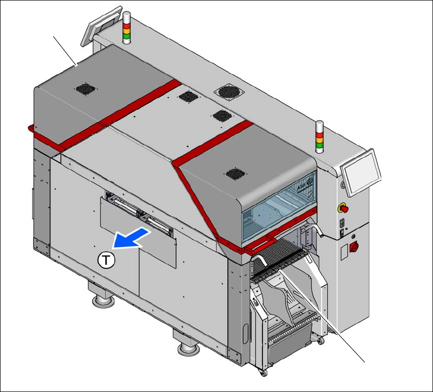
Two SIPLACE TX component trolleys can be docked onto SIPLACE TX placement machines.
3
Fig. 3.9 - 1 Component trolley locations
(1) Location 1
(2) Location 2 with optional 7" tape reel holder
(T) Direction of PCB transport
The component trolleys are stand-alone modules that can be set up with feeders at an external
setup area. This means that the production process only has to be interrupted briefly in order to
change the component trolley. The component trolley has 5 holders in total. Each tape reel holder
can accommodate 2 tape reels, so that up to ten 13" (optional 7") tape reels can be positioned
above the tape container.
(2)
(1)
3 Technical data and assemblies User manual SIPLACE TX V2
3.9 Component trolley From software version 711.1 04/2018
148
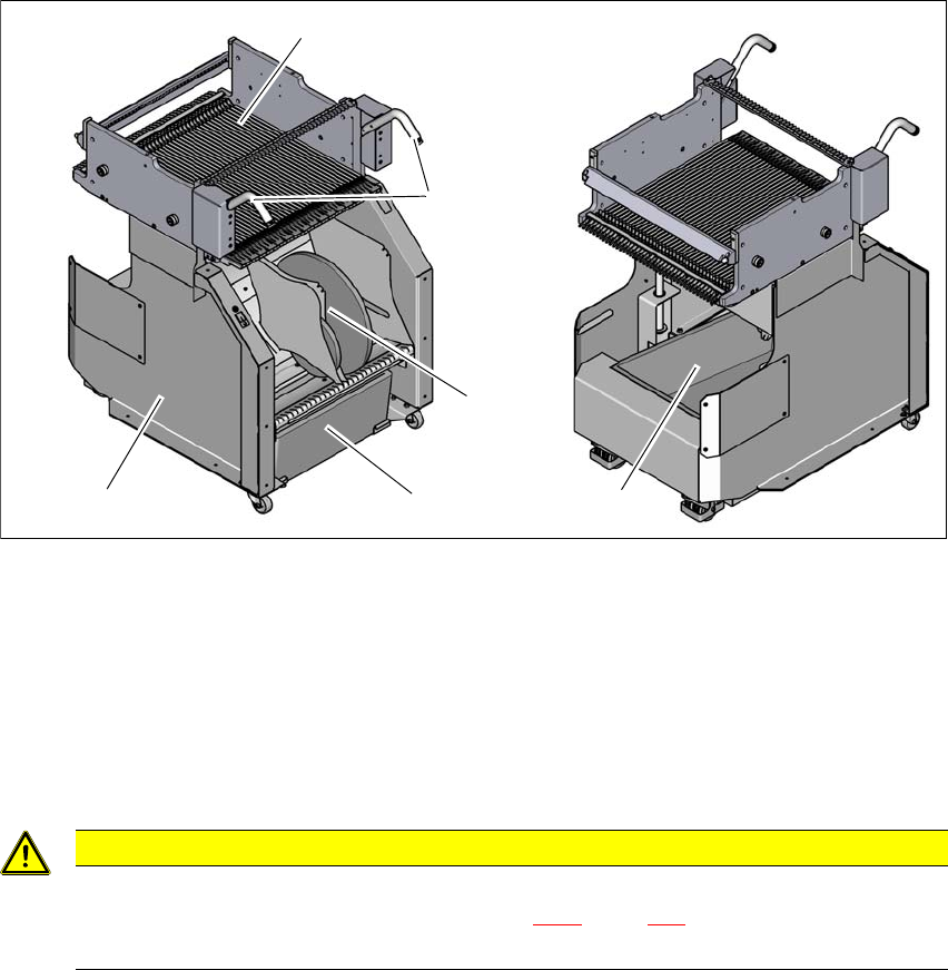
3.9.1 Structure
The component trolley essentially consists of the chassis, the changeover table for holding the
feeder modules, the tape reel container and the waste tape container. The pullout waste tape con-
tainer can be found beneath the chassis. The cut waste tape travel down a chute into the waste
tape container, which must be emptied as it fills up.
3
Fig. 3.9 - 2 Component trolley, SIPLACE TX-Series, front and rear view
(1) Changeover table with 40 tracks
(2) Handles
(3) Waste tape container
(4) Tape reel container with 13" tape reels
(5) Chassis
3
CAUTION
Observe the safety instructions!
Observe the safety instructions in section 5.8.2, page 230 when you pull the tape re-
ject bin out of the component trolley.
(1)
(2)
(3)
(4)
(3)
(5)