00198442-01_UM_TX-V2_EN.pdf - 第163页
User manual SIPLACE TX V2 4 Setting up and commissioning From software version 711.1 04/2018 4.2 Configuration when delivered 163 4 Fig. 4.2 - 4 Contact surfaces - Forks parallel to the direction of PCB transport on the …
4 Setting up and commissioning User manual SIPLACE TX V2
4.2 Configuration when delivered From software version 711.1 04/2018
162
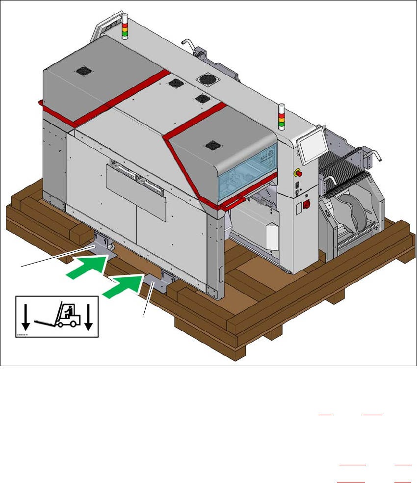
4.2.6 Lifting the placement machine off the pallet
4
Fig. 4.2 - 3 Contact points for transportation with the fork-lift
(1) Shipping braces with steel spacer
During transportation, always follow the safety instructions in section 4.1, page 155).
Loosen the two shipping braces (1) on the pallet. The two braces and the steel spacers re-
main fitted to the placement machine.
Loosen and remove the shipping braces on the opposite side (item 2 in fig. 4.2 - 1, page 159).
The machine may ONLY be lifted with a fork-lift on the side (item A in fig. 4.2 - 3, page 162)
on which the output end of the machine is located.
(A)
1
1
User manual SIPLACE TX V2 4 Setting up and commissioning
From software version 711.1 04/2018 4.2 Configuration when delivered
163
4
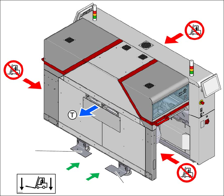
Fig. 4.2 - 4 Contact surfaces - Forks parallel to the direction of PCB transport on the output side
(T) Direction of travel for PCB conveyor
(1) Fork-lift forks between the machine feet
(2) Never lift the machine at the input side! Risk of tilting!
(3) Never lift the machine at the component trolley locations with a fork-lift! Risk of tilting!
(4) Shipping braces with steel spacer
Position the fork-lift at cross-angles to the direction of conveyor transport (at the output end).
Open the forks until the forks are between the two placement machine feet and the contact
surfaces of the placement machine lie evenly on the forks.
Push the forks between the contact surfaces of the placement machine (machine frame) and
over the steel spacers for the shipping braces. The steel spacers are used as an additional
safety measure to prevent the placement machine from tilting.
Push the forks fully under the placement machine, so that these are positioned properly on
the machine frame of the opposite side.
Lift the placement machine off the pallet.
(2)
(1)
(3)
(3)
(4)
(4)

4 Setting up and commissioning User manual SIPLACE TX V2
4.3 Transporting the placement machine From software version 711.1 04/2018
164
Transport the placement machine to its target position in your production environment.
Place the placement machine in the line (see section 4.5.5, page 181).
4.2.7 Delivery configuration for placement machine
The machine is configured as follows when delivered:
– The lanes of the dual conveyor are set to a width of 210 mm. This width setting will be import-
ant when fine-tuning the placement machine.
– Both monitors are dismantled.
– Both indicator lamps are dismantled.
– All gantry axes are fixed with shipping braces (see section 4.6
, page 193).
4.3 Transporting the placement machine
The machine may only be lifted and transported with the fork-lift at the output side. The diagram
4.2 - 4
, page 163 shows the fork-lift attachment points on the placement machine for lifting the
placement machine off the pallet or transporting it without the pallet.
4
4.3.1 Safety instructions during placement machine transportation
During transportation, always follow the safety instructions in section 4.1, page 155).
4
PLEASE NOTE
If the machine is at its place of final use and should be integrated into a line, it may also
be lifted to the actual locations with a pallet truck. See also section 4.5.5
, page 181).