00198442-01_UM_TX-V2_EN.pdf - 第139页
User manual SIPLACE TX V2 3 Technical data and assemblies From software version 711.1 04/2018 3.8 SIPLACE tape feeder modules for SIPLACE TX 139 3.8.1.4 Design of the SIPLACE SmartFeeder Xi 3 The following diagram shows …
3 Technical data and assemblies User manual SIPLACE TX V2
3.8 SIPLACE tape feeder modules for SIPLACE TX From software version 711.1 04/2018
138
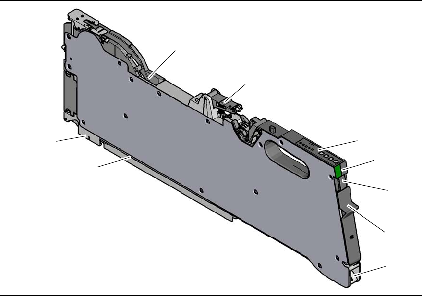
3.8.1.3 Design of the SIPLACE SmartFeeder X
The following diagram shows the design of the SIPLACE SmartFeeder X.
3
Fig. 3.8 - 1
SIPLACE SmartFeeder X
(1) Entry to the tape guide channel with tape spring
(2) Flap on cover foil container
(3) Removal handle, engaged
(4) Status display
(5) Operating panel - LED display
(6) Foil rocker
(7) Tape guide channel outlet
(8) Front slider guide
(9) Back slider guide
(1)
(2)
(3)
(4)
(5)
(6)
(8)
(9)
(7)
User manual SIPLACE TX V2 3 Technical data and assemblies
From software version 711.1 04/2018 3.8 SIPLACE tape feeder modules for SIPLACE TX
139
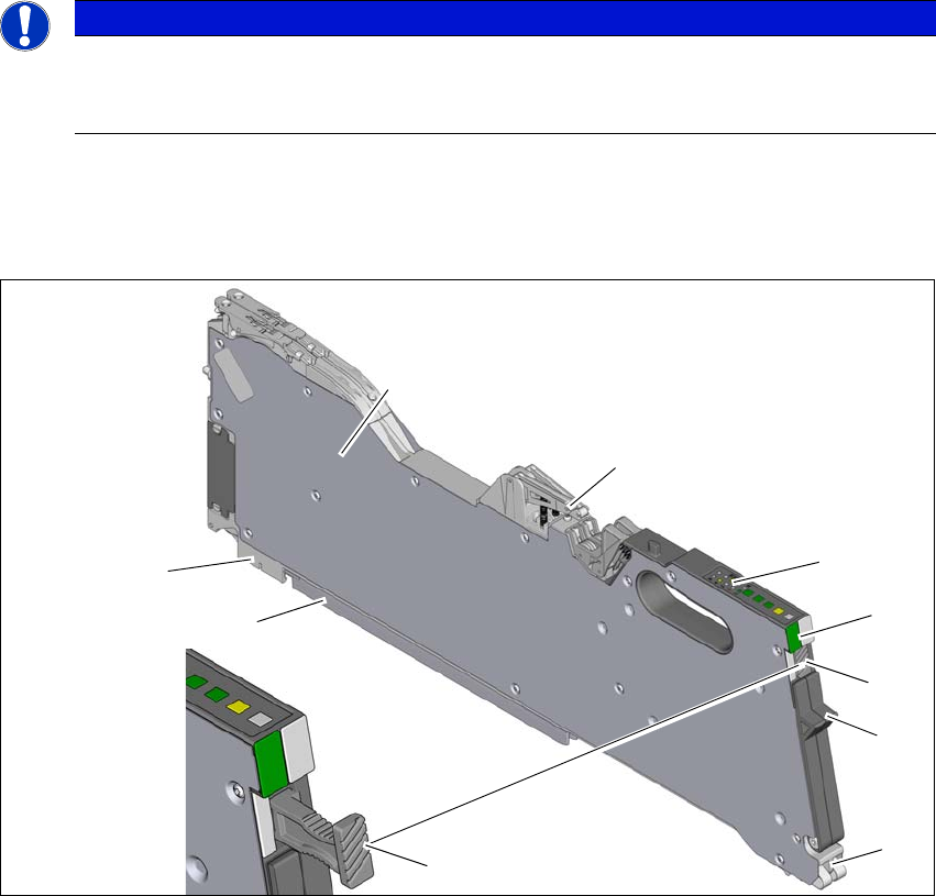
3.8.1.4 Design of the SIPLACE SmartFeeder Xi
3
The following diagram shows the design of the SIPLACE SmartFeeder Xi, using the example of
the SIPLACE SmartFeeder 2 x 8 mm Xi. The SIPLACE SmartFeeder Xi can be recognized by its
slanted and grooved surface on the removal handle.
3
Fig. 3.8 - 2 SIPLACE SmartFeeder 2 x 8 mm Xi
(1) Entry to the tape guide channel with tape spring
(2) Flap on cover foil container
(3) Removal handle, docked (grooved surface)
(4) Status display
(5) Operating panel - LED display
(6) Foil rocker
(7) Tape guide channel outlet
(8) Front slider guide
(9) Back slider guide
PLEASE NOTE
Maximum speed with SIPLACE SmartFeeder Xi.
The SpeedStar C&P20 P can only reach maximum speed in conjunction with the SI-
PLACE SmartFeeder Xi.
(1)
(2)
(3)
(4)
(5)
(6)
(8)
(9)
(7)
(3)

3 Technical data and assemblies User manual SIPLACE TX V2
3.8 SIPLACE tape feeder modules for SIPLACE TX From software version 711.1 04/2018
140
3.8.1.5 Technical data for SIPLACE tape feeder modules
In general, the SIPLACE tape feeder modules have a length of approx. 587 mm and a height of
approx. 200 mm. The technical data are listed in the following table.
The maximum height of the interference contours above the upper edge of the tape pocket is ≤ 3
mm. As the SIPLACE tape feeder modules do not show any flaps projecting upwards and are also
fixed to the changeover tables, the risk of a head crash is reduced to a minimum.
Tape feeder module
*a
Item no. L x H
[mm]
Width
[mm]
Location
occupied
Transport
increment
[mm]
Max. tape
height
[mm]
*b
SIPLACE SmartFeeder 4 mm X 00141368 587x200 10,8 1 1 1,1
With splice sensor
00141388
SIPLACE SmartFeeder 2 x 8 mm X 00141269 587x200 22,6 2 1/2/4/8 3,5
With splice sensor 00141289
SIPLACE SmartFeeder 8 mm X 00141370 587x200 10,8 1 1/2/4/8 3,5
With splice sensor 00141390
SIPLACE SmartFeeder 4 mm Xi
00141478
587x200 10,8 1 1 1,1
With splice sensor 00141498
SIPLACE SmartFeeder 2x8 mm Xi
00141479
587x200 22,6 2 1/2/4/8 3,5
With splice sensor
00141500
SIPLACE SmartFeeder 8 mm Xi
00141480
587x200 10,8 1 1/2/4/8 3,5
With splice sensor
00141500
SIPLACE SmartFeeder 12 mm X 00141371 587x200 22,6 24 - 16
*c
6,5
With splice sensor 00141391
SIPLACE SmartFeeder 16 mm X 00141372 587x200 22,6 2 4 - 20
*c
25
With splice sensor 00141392
SIPLACE SmartFeeder 24 mm X
00141373 587x200 34,4 3 4 - 32
*c
25
With splice sensor
00141393
SIPLACE SmartFeeder 32 mm X
00141374 587x200 46,2 4 4 - 40
*c
25
With splice sensor
00141394
SIPLACE SmartFeeder 44 mm X
00141375 587x200 58,0 5 4 - 52
*c
25
With splice sensor
00141395
SIPLACE SmartFeeder 56 mm X
00141376 587x200 69,8 6 4 - 64
*c
25
With splice sensor 00141396
SIPLACE SmartFeeder 72 mm X --
587x200 81,6 7 4 - 80
*c
25
With splice sensor 00141397
SIPLACE SmartFeeder 88 mm X --
587x200 105,2 9 4 - 96
*c
25
With splice sensor 00141398
SIPLACE SmartFeeder 104mm X --
587x200 128,9 11 4 - 96
*c
25
With splice sensor 00141399
Tape reels Diameter up to 483 mm (19")
Changeover time ≤ 8 s
*)a SIPLACE SmartFeeder 72 mm, 88 mm and 104 mm have not been tested with the SIPLACE TX.
*)b For 8 mm paper tapes, the paper thickness must not exceed 1.6 mm. The length of a component pocket in the direction of
tape travel may not exceed 51 mm.
*)c In 4mm steps