00198442-01_UM_TX-V2_EN.pdf - 第20页
1 Introduction User manual SIPLACE TX V2 1.3 Placement machine description From software version 711.1 04/2018 20 1.3.1 Placem ent H ead Configurations 1 CPP_H = Multistar CPP in high assembly position CPP_L = Multistar …

User manual SIPLACE TX V2 1 Introduction
From software version 711.1 04/2018 1.3 Placement machine description
19
1.3 Placement machine description
The innovative high-end placement platform SIPLACE TX achieves new benchmarks in place-
ment performance and productivity per area. The compact design of the SIPLACE TX supports
precise scaling of line performance in small steps.
Three placement methods are possible for processing the components:
– Collect&Place,
– Pick&Place and
– A combination of Collect&Place and Pick&Place (mixed mode).
These can be quickly and accurately positioned by linear motors, moving independently of one
another in the X and Y directions.
1
1
The SIPLACE TX placement machines have one placement area and a dual conveyor. Two
boards can be placed at the same time on dual conveyors.
There are two locations available for supplying components. These can be fitted with component
trolleys and configured with up to 40 tracks.
Type Description
SIPLACE TX1
– Placement machine with one gantry
– Table position "outside" at location 1
– Table position "inside" at location 2 with short cover
SIPLACE TX2
– Placement machine with two gantries
– Table position "outside" at location 1
– Table position "inside" at location 2 with short cover
SIPLACE TX2i
– Placement machine with two gantries
– Table position "innermost position" at location 1 and 2
– Short covers at location 1 and 2 for optimum ease of use
– Narrow nozzle changer with 3 magazines
PLEASE NOTE
Table position "innermost position" for SIPLACE TX2i
The table positions for the SIPLACE TX2i have been moved even further inwards than
the position "inner" used for the SIPLACE TX1 V2/TX2 V2.

1 Introduction User manual SIPLACE TX V2
1.3 Placement machine description From software version 711.1 04/2018
20
1.3.1 Placement Head Configurations
1
CPP_H = Multistar CPP in high assembly position
CPP_L = Multistar CPP in low assembly position
Machine Placement head Standard cameras Options
SIPLACE
TX1
C&P20 P2 Component camera, type 48 --
CPP_L Component camera, type 30 Component camera, type 45
CPP_H
Component camera, type 30 Component camera, type 45
Stationary camera, type 33 (only at
location 1)
TH Stationary camera, type 33
(only at location 1)
Stationary camera, type 25 (only at
location 1)
SIPLACE
TX2
C&P20 P2 / C&P20 P2 Component camera, type 48 --
CPP_L/CPP_L Component camera, type 30 Component camera, type 45
CPP_H / CPP_H
Component camera, type 30 Component camera, type 45
Stationary camera, type 33 (only at
location 1)
TH / CPP_H
Stationary camera, type 33
(only at location 1)
Stationary camera, type 25 (only at
location 1)
Component camera, type 30 Component camera, type 45
SIPLACE
TX2i
C&P20 P2 / C&P20 P2 Component camera, type 48 --
CPP_L/CPP_L Component camera, type 30 Component camera, type 45
CPP_H / CPP_H Component camera, type 30 Component camera, type 45
User manual SIPLACE TX V2 1 Introduction
From software version 711.1 04/2018 1.3 Placement machine description
21
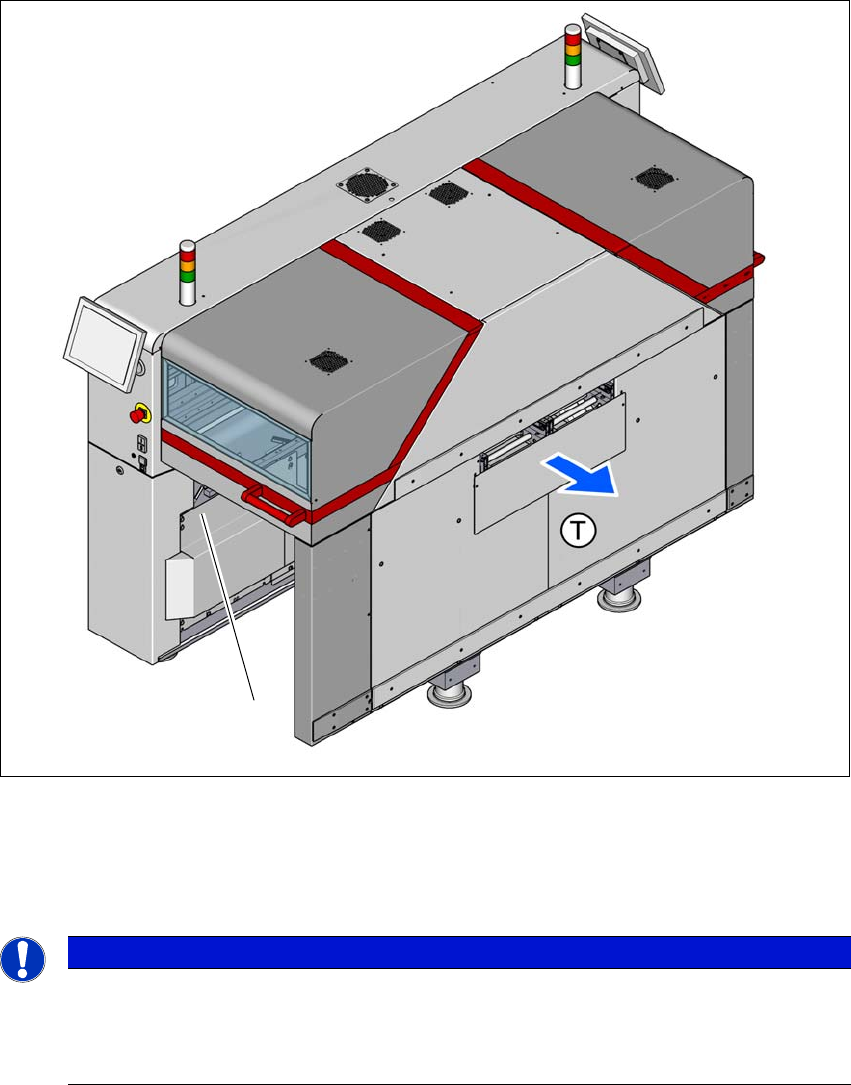
1.3.2 Placement machine serial number
The serial number of the machine can be found on the typeplate, on the inside of the placement
machine frame at location 1.
1
Fig. 1.3 - 1 Position of typeplate with serial number
(T) Direction of travel
(1) Typeplate
1
PLEASE NOTE
Electrical ratings on the typeplate
The electrical ratings on the typeplate are maximum values. The electrical power actually
consumed depends on the placement machine configuration and the placement pro-
gram.
(1)