00198442-01_UM_TX-V2_EN.pdf - 第188页
4 Setting up and commissioning User manual SIPLACE TX V2 4.5 Setting up the placement machine From software version 711.1 04/2018 188 4.5.7.1 Adjusting the placement machine 4 Fig. 4.5 - 6 Adjusting the machine Place t…

User manual SIPLACE TX V2 4 Setting up and commissioning
From software version 711.1 04/2018 4.5 Setting up the placement machine
187
4
4
Loosen the three other placement machine feet (2) in the same way.
Use the 18 mm open-end wrench, to change the height of the placement machine feet (2)
with the setting screw (1), in order to reach the relevant conveyor height.
4
Adjust the placement machine (see section 4.5.7.1, page 188).
WARNING
Only loosen the clamping screws with the attachable ratchet
The clamping screws may not be loosened using the torque wrench. There is a risk of
causing injuries.
To loosen the clamping screws, only use the attachable ratchet with the appropriate
extension.
WARNING
Perform work only with the bump cap and protective gloves.
There is a risk of causing injuries to the head and hands.
Only perform work with the bump cap and protective gloves.
PLEASE NOTE
Position of setting screws for height adjustment
On the output side, the setting screws are next to the component inserts.
On the input side, the setting screws are concealed, under the power supply unit. If the
optional vacuum pump is fitted, the other setting screw is hidden by the vacuum pump
and is located below this.
4 Setting up and commissioning User manual SIPLACE TX V2
4.5 Setting up the placement machine From software version 711.1 04/2018
188
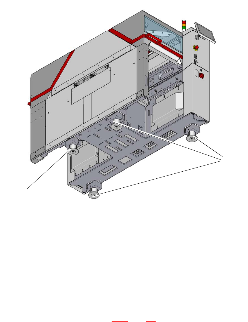
4.5.7.1 Adjusting the placement machine
4
Fig. 4.5 - 6 Adjusting the machine
Place the placement machine spirit level (measuring accuracy of 0.02 mm) on the unclamped
lifting table and measure in the X and Y directions.
Align the placement machine in the X and Y direction, using the machine spirit level, at the
three machine feet (1). The maximum permissible deviation is 0.10 mm/m.
Then fix the fourth machine foot (2) so that it is firmly on the ground.
Check the load-bearing strength of the 4 placement machine feet. The 4 placement machine
feet must all touch the ground and be evenly loaded.
The setting screws for adjusting the height of the placement machine feet must be positioned
in a load-bearing state, once the placement machine has been aligned.
Use the torque wrench to tighten the clamping screws (torque of 130 Nm) for the four place-
ment machine feet. (See also diagram 4.5 - 5
, page 186)
Hit the feet with a hammer to check the load-bearing strength of the placement machine feet.
Use the spirit level to check that the placement machine is accurately aligned.
(2)
(1)

User manual SIPLACE TX V2 4 Setting up and commissioning
From software version 711.1 04/2018 4.5 Setting up the placement machine
189
4.5.7.2 Aligning and adjusting the placement machines in the line
Use the pallet truck to move the placement machine to its rough position and then lower the
placement machine into position. While doing this, observe the safety instructions and proce-
dural instructions in section 4.5.5.1
, page 182.
Align the placement machine vertically (height) and horizontally with the help of the machine
spirit level.
Position the placement machine so that there is a smooth transition between the PCB con-
veyors for the adjacent placement machine.
Check the height and horizontal position and correct, if necessary.
Check the transition between the PCB conveyors and correct, if necessary.
If both are OK, use the torque wrench to tighten the clamping screws (torque of 130 Nm) for
the four placement machine feet. (See also diagram 4.5 - 5
, page 186)
4.5.7.3 Aligning the placement machine with the air cushion transport system
Place the three air cushions from the air cushion transport system under the contact points
(see fig. 4.5 - 7
, page 190).
4
Raise the placement machine and align it with respect to the line.
Check the distance from the PCB conveyor system of the adjacent placement machine. It
should be between 1 mm and 3 mm.
Lower the placement machine.
WARNING
Avoid swinging up of the placement machine - observe the instruction manual for the air
cushion transportation system!
Observe the handling and safety instructions in the user manual for the air cushion
transport system.
Regulate the supply of air very carefully, to prevent the placement machine from
swinging up.