00190802-02.pdf - 第184页
6 Product / Package Form User’s Manual Line Computer UNIX 6.1 Package Form Editor Software Version 402.xx Edition 03/97 6 - 10 - Pin/Ba ll This co mmand p er mits the window for the descr iptio n of the mod el data for a…
User’s Manual Line Computer UNIX 6 Product / Package Form
Software Version 402.xx Edition 03/97 6.1 Package Form Editor
6 - 9
6.1.2.4 Package Form Editor Command Area - Setting "Vision data"
☞
NOTE
The command area is not displayed if the current package form is of the "PDC" type (see Fig. 6.1.2).
In the command area (see Fig. 6.1.1) only the "Create" command can initially be selected. The remaining
commands cannot be activated until an already-created pin or grid group is selected from the view area.
COMMANDS
The procedures for executing the commands are described in the following.
-
Create
A new pin group (see section 6.1.2.7) or a new grid group (see section 6.1.2.8) can be created.
●
Click on Create.
The window for the description of the new pin or grid group is opened (see Fig. 6.1.7 and
Fig. 6.1.11).
-
Delete
A selected pin or grid group can be deleted.
●
In the display area, select any pin or ball of the group you wish to delete. The selected group is
displayed, surrounded by a rectangle.
●
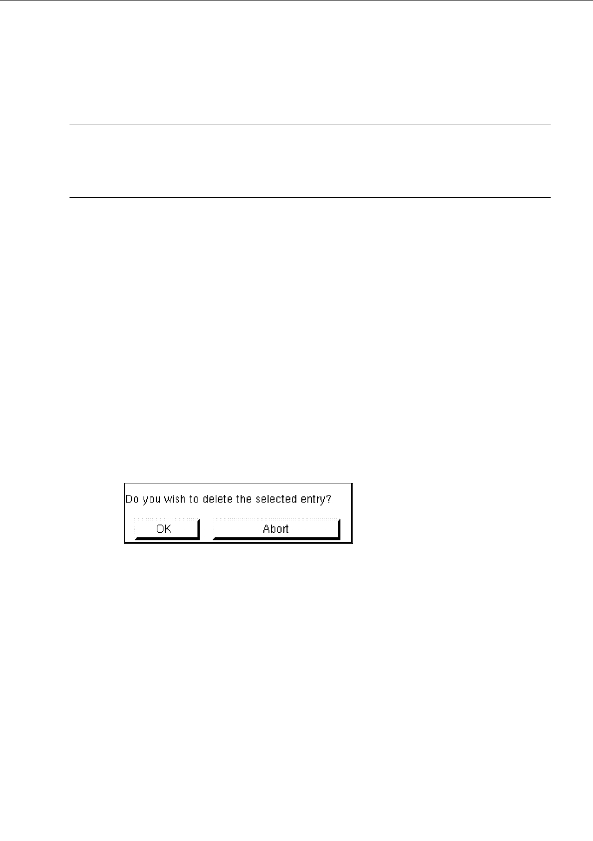
Click on Delete.
The following dialog box is opened.
●
Click on OK in the dialog box.
The dialog box is closed. The group is no longer displayed in the display area.
-
Group
This command permits the window for the description of the group data for a selected object (pin
group/grid group) to be opened.
●
From the view area select the group whose group data you wish to edit.
The selected group is surrounded by a rectangle.
●
Click on Group.
The window for the description of the group data is displayed on the screen (see Fig. 6.1.7 or
Fig. 6.1.11).

6 Product / Package Form User’s Manual Line Computer UNIX
6.1 Package Form Editor Software Version 402.xx Edition 03/97
6 - 10
-
Pin/Ball
This command permits the window for the description of the model data for a selected object
(pin/ball) to be opened.
●
From the view area select the group containing the object (pin/ball) whose model data you wish to
edit.
The selected group is surrounded by a rectangle.
●
Click on
Pin/Ball
.
The window for the description of the model data is displayed on the screen (see Fig. 6.1.8 or
Fig. 6.1.12).
6.1.2.5 Package Form Editor Editing Fields - Setting "Vision data"
☞
NOTE
When an existing GF-file is opened upon the start-up of the Package Form Editor, the factory or customer
defined default values are contained in the editing fields described below.
Editing field "Nominal dimensions"
-
X +/-
[mm] component length, with indication of the tolerances
see Fig. 6.1.5 or Fig. 6.1.9
-
Y +/-
[mm] component width, with indication of the tolerances
see Fig. 6.1.5 or Fig. 6.1.9
-
Z +/-
[mm] component height, with indication of the tolerances
see Fig. 6.1.6 or Fig. 6.1.9
☞
NOTE
The length of a component refers to the x-direction and its width to the y-direction since the position of the
component (in the Vision System) is so defined that "pin 1" is located at the bottom on the left (see Fig.
6.1.5 and Fig. 6.1.9).
Editing Area "Body"
☞
NOTE
This field is not
displayed if the current package form type is a "PDC" (see Fig. 6.1.2) or a "BGA" (see Fig.
6.1.3) since with these types the dimensions of the package body correspond to the nominal dimensions.
-
X
[mm] length of package body (see Fig. 6.1.6)
-
Y
[mm] width of package body (see Fig. 6.1.6)

User’s Manual Line Computer UNIX 6 Product / Package Form
Software Version 402.xx Edition 03/97 6.1 Package Form Editor
6 - 11
Editing field "Packaging tolerance"
-
X
[mm] max. permissible positional tolerance of the component in the
package in x-direction
-
Y
[mm] max. permissible positional tolerance of the component in the
package in y-direction
-
Angle
[Degree] max. permissible deviation from the 0-degree position of the
component (rotational angle in the package)
Editing field "Acceptance limits" (only FDC and BGA)
☞
NOTE
When the Package Form Editor is opened for a new package form, the editing fields of this area already
contain the default values for the spacing and row tolerances.
In the case of the "BGA" package form type (see Fig. 6.1.3) only the "Spacing" editing field is available.
-
Spacing
[mm] Max. permissible value for pin spacing deviation
(spacing ^
distance between pin(ball) centers)
If the value for the pin spacing error limit is exceeded (i.e. the
leads of an "FDC" are bent at the sides)
the component is identified as defective by the Vision System
and excluded from the placement program.
-
Row
[mm] Max. permissible offset of opposite identical rows of
a "FDC" (i.e., max. permissible symmetric deviation)
-
Cubic component
[mm] Description see section 6.1.2.3
☞
NOTE
When the Package Form Editor is opened for the definition of a new package form, the editing fields
"Nominal dimensions" and "Packaging tolerance" are blank, only the editing area "Acceptance limits"
already contains the default values".