00190802-02.pdf - 第240页
8 Product / PCB User’s Manual Line Computer UNIX 8.1 PCB Editor Software Version 402.xx Edition 06/ 96 8 - 22 Frame around a selecte d placeme nt pos ition and /or substr ucture The fram e marks th e outline of the c urr…

User’s Manual Line Computer UNIX 8 Product / PCB
Software Version 402.xx Edition 06/96 8.1 PCB Editor
8 - 21
8.1.3.8 Symbols and Their Meanings in the Structure Editor (Graphic Mode)
In the Graphic Mode of the PCB Editor a series of symbols are used each of which has a different meaning.
In the following, the meaning of the symbols is explained.
Outline (dimensions) of the PCB
It is uniquely defined by the length and width of the PCB or substructure.
Name of the PCB or the PCB substructure (color blue)
<Name> The name is always displayed above the upper left corner of the outline, with the same orientation
as the substructure.
Zero point
This symbol identifies the zero point of the coordinate system of the PCB or substructure.
Coordinate system of a substructure
This graphic indicates the position of the coordinate system of the substructure.
The arrow marks the x-axis and always identifies the positive direction of the axis.
Dimensional vectors
They symbolize the two vectors from the PCB zero point to corner "1" and corner "2" of the PCB
outline (see graphical display on page 8 - 25).
Offset vector
connects the zero point of a substructure to the zero point of the superior substructure and hence
corresponds to the offset or displacement vector between the two coordinate systems of these
substructures.
PCB fiducial
This symbol indicates the position of a PCB-related fiducial.
It is always displayed in the shape of a double cross, irrespective of the actual shape of the fiducial.
Ink spot
●
This symbol indicates the position of the fiducials defined as inkspots.
It is always displayed in the shape of a dot, irrespective of the actual shape of the fiducial.
Placement position (color green)
This symbol indicates the position of the placement position or the zero point of the coordinate
system of the placement position.
Placement position fiducial
This symbol indicates the position of a PP-related fiducial.
It is always displayed in the shape of a double cross, irrespective of the actual shape of the fiducial,
and it is significantly smaller than the symbol of a PCB fiducial.
8 Product / PCB User’s Manual Line Computer UNIX
8.1 PCB Editor Software Version 402.xx Edition 06/96
8 - 22
Frame
around a selected placement position and/or substructure
The frame marks the outline of the currently selected substructure.
The frame marks the currently selected placement position.
Frame
around placement position(s) or a substructure
The frame marks the outline of a substructure which is linked to the currently selected sub-
structure.
The frame marks the placement positions which are linked to the currently selected placement
position.
8.1.4 Cluster Editor Window
A Cluster Editor can be opened for each PCB type generated (see description on page 8 - 10).
In the following, the different areas of the Cluster Editor window and their functions are explained.
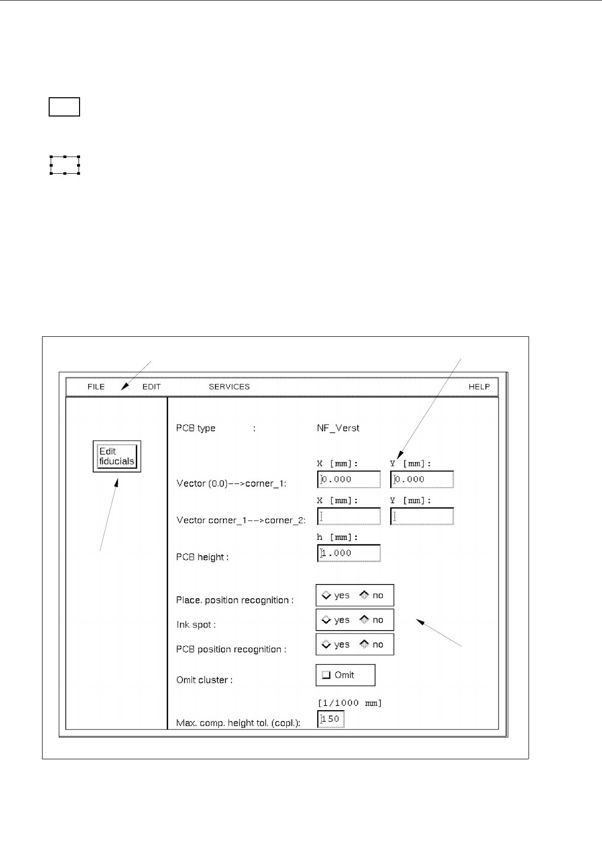
Fig. 8.1.8 Window "Cluster Editor"
menu bar
editing area
command button
setting area

User’s Manual Line Computer UNIX 8 Product / PCB
Software Version 402.xx Edition 06/96 8.1 PCB Editor
8 - 23
The window is subdivided as follows:
-
Menu bar
-
Editing area
-
Setting area
-
Command button
Menu Bar
The menu bar contains the menus "FILE", EDIT", "SERVICES" and "HELP".
A detailed description of the "EDIT" menu is contained in section 8.1.4.1 and a description of the "SERVICES"
menu is contained in section 8.1.4.2.
☞
NOTE
Since the functions and operation of the "FILE" and "HELP" menus are similar to those in other application
programs of the line computer, they are described comprehensively in chapter 2.
Editing area
(see section 8.1.4.3)
All PCB-specific data that are required for the description of a PCB, the so-called cluster, are entered in this area.
-
The cluster description contains the following data:
-
Dimensions of the PCB such as length, width and height
-
Process data for the production of the PCB, such as PP position recognition on/off, ink spot recogni-
tion on/off, PCB position recognition on/off, placement on/off (omit cluster) and the max. component
height tolerance for the coplanarity measurement
-
Fiducial sets and fiducials
Setting area
(see section 8.1.4.4)
The operational sequence of the placement process can be defined in this area by activating/deactivating the
respective buttons (e.g. assembly with or without PCB position recognition).
"Edit fiducials" command button
The window of the Fiducial Editor is opened by clicking on this button (see Fig. 8.1.10).