00190802-02.pdf - 第236页
8 Product / PCB User’s Manual Line Computer UNIX 8.1 PCB Editor Software Version 402.xx Edition 06/ 96 8 - 18 8.1.3.5 Display of the Cluster Data in the Struct ure Editor (Graphic Mode) In the Graphic Mode of the Str uct…
User’s Manual Line Computer UNIX 8 Product / PCB
Software Version 402.xx Edition 06/96 8.1 PCB Editor
8 - 17
Settings:
-
Setting the zoom factor
●
Click on the editing field and enter the desired value (10 to 999).
●
To accept the entry, press the RETURN key.
The PCB is displayed in the desired size.
-
Turning the placement position display on/off
This option serves to toggle the display of the placement positions (PPs) to the on or off state. By
default, the display of the PPs is turned on.
●
Click on icon .
If the display of the PPs was turned on, the PPs are no longer displayed now, and the icon is mar-
ked by a red cross.
-
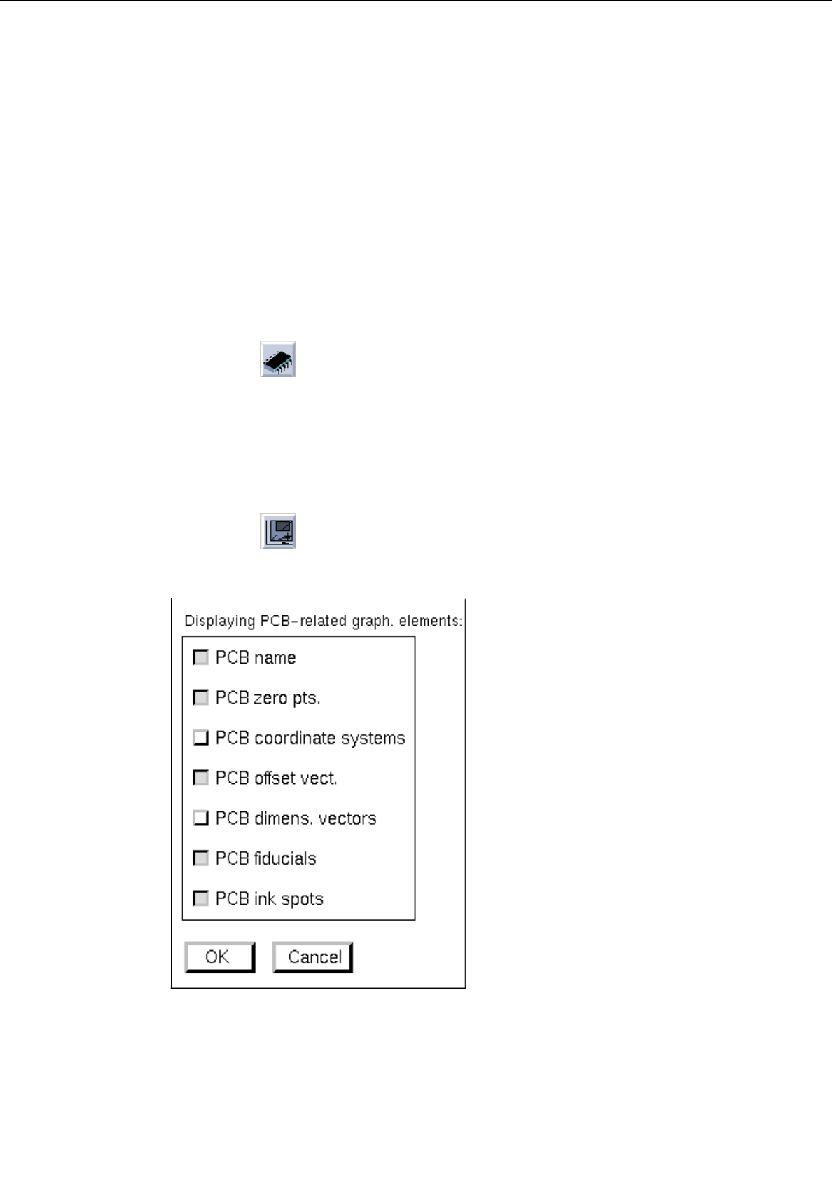
Selecting display options
To obtain a clearly arranged display of the PCB, the respectively required graphical elements can be
selected individually (e.g. only the display of the PCB fiducials).
●
Click on icon .
The following dialog box is opened:
●
Activate or deactivate the desired display options (graphical elements) by clicking on the
respective buttons.
●
Click on
OK
.
The dialog box is closed, and the PCB with the selected graphical elements is displayed in the
display area (see Fig. 8.1.6).
8 Product / PCB User’s Manual Line Computer UNIX
8.1 PCB Editor Software Version 402.xx Edition 06/96
8 - 18
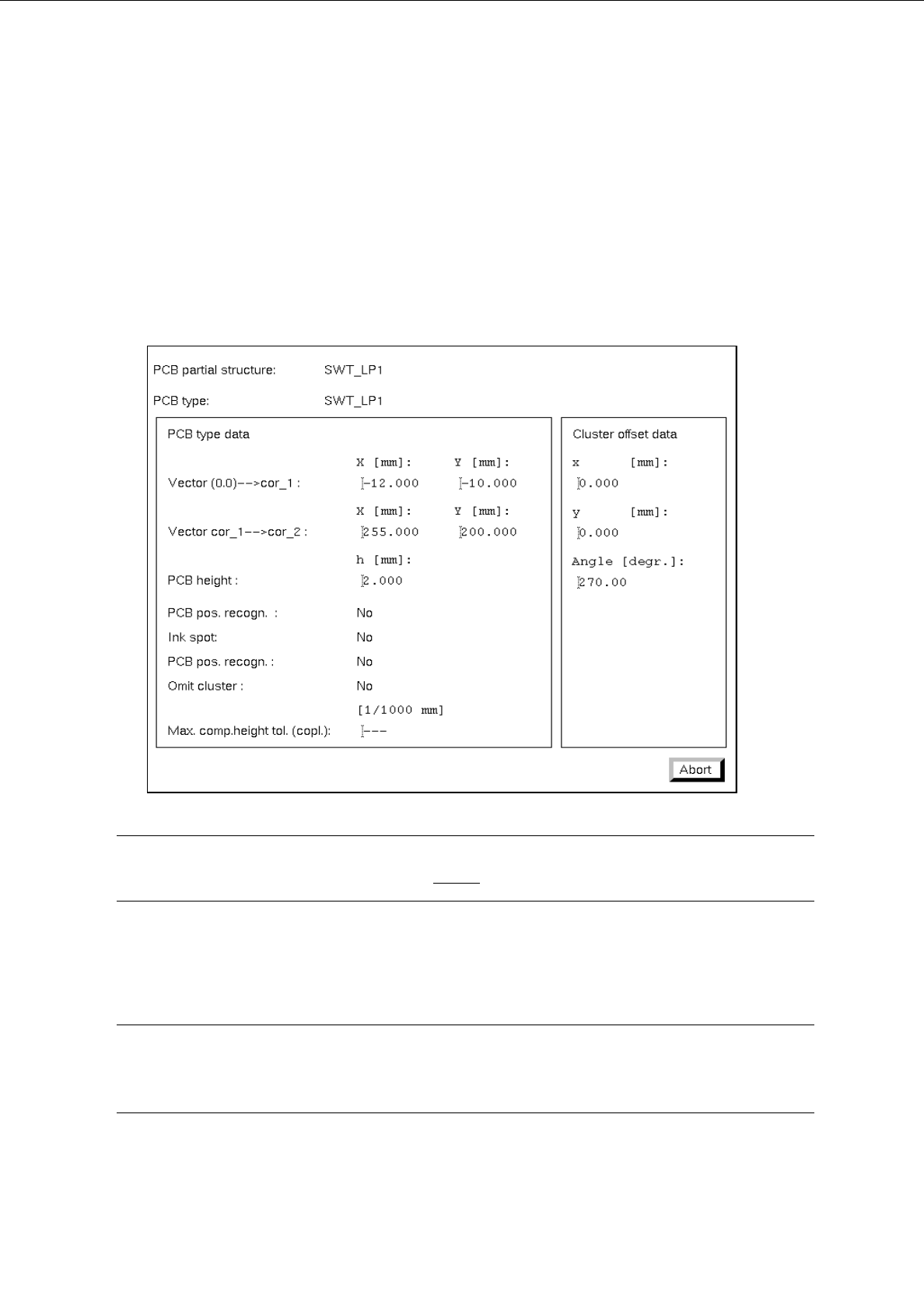
8.1.3.5 Display of the Cluster Data in the Structure Editor (Graphic Mode)
In the Graphic Mode of the Structure Editor the cluster data of the PCB and those of every substructure can
be displayed in separate windows.
●
Select the outline of the PCB structure by double-clicking on it.
The outline is highlighted by a selection frame in bold type.
The "PCB info" window containing the cluster data of the selected structure is opened.
☞
NOTE
The data contained in the "PCB info" window cannot be changed.
●
Click on the Abort button.
The "PCB info" window is closed.
☞
NOTE
In addition, the "PCB info" window can be opened for a substructure from the "PP information"
window (see page 8 - 19).
User’s Manual Line Computer UNIX 8 Product / PCB
Software Version 402.xx Edition 06/96 8.1 PCB Editor
8 - 19
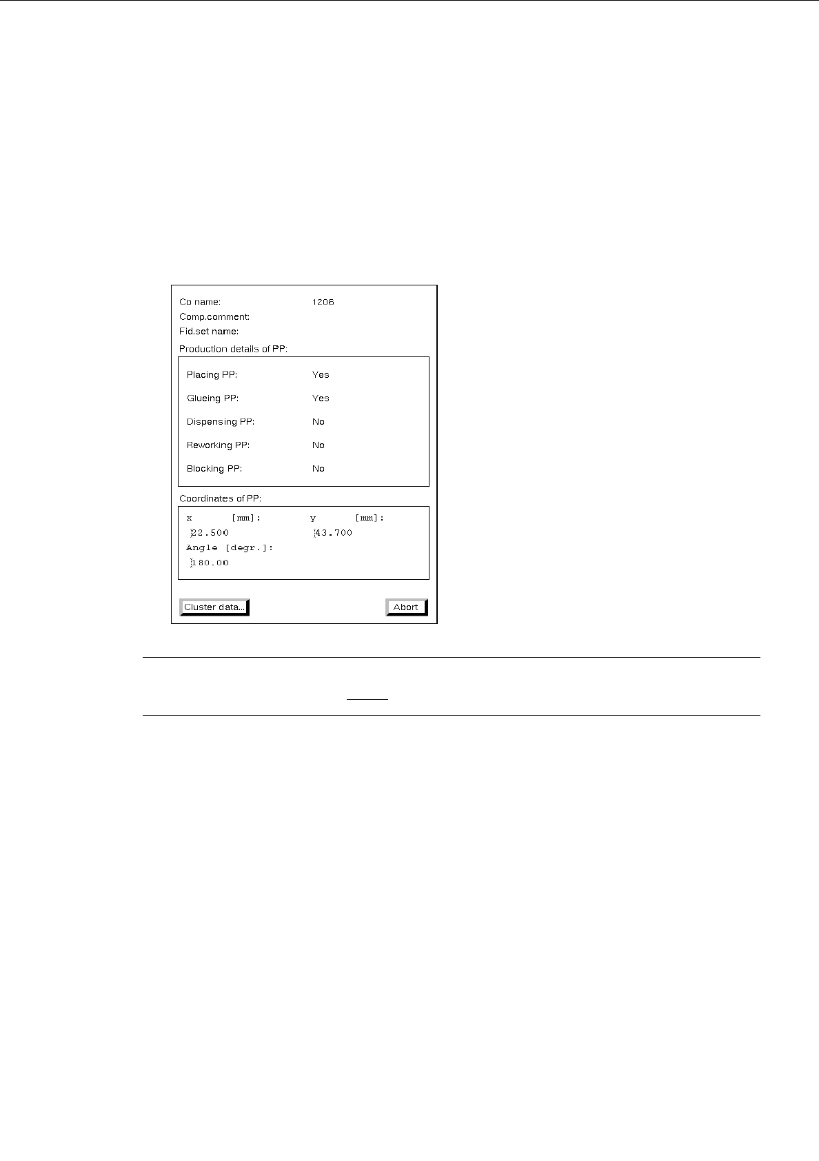
8.1.3.6 Display of PP-Data in the Structure Editor (Graphic Mode)
The data of a selected placement position can be displayed in a separate window in the Graphic Mode of the
Structure Editor.
●
Select the desired placement position by double-clicking.
The placement position is surrounded by a frame in bold type.
The "PP information" window containing the data of the selected placement position is opened.
☞
NOTE
The data in the "PP information" cannot be changed.
-
Cluster data...
This button permits the "PCB info" window to be opened that contains the cluster data of the sub-
structure in which the selected placement position is located.
●
Click on the Cluster data... button.
The "PCB info" window is opened.
●
Click on the Abort button in the "PCB info" window.
The "PCB info" window is closed.
●
Click on the Abort button in the "PP information" window.
The "PP information" window is closed.