00190802-02.pdf - 第205页
User’s Manual Line Computer UNIX 6 Product / Package Form Software Version 402.xx Edition 03/97 6.1 Package Form Editor 6 - 31 Fig. 6.1.14 Selection Windo w of the "Sensor T ype" ● Clic k on de sire d type . Th…
6 Product / Package Form User’s Manual Line Computer UNIX
6.1 Package Form Editor Software Version 402.xx Edition 03/97
6 - 30
6.1.2.10 Package Form Editor Command Area - "Handling data" Display
In the command area (see Fig. 6.1.4) two different tools can be selected from (nozzle or sensor type) that can
be created or deleted by means of the corresponding commands. The desired tool type desired is selected by
clicking on the button adjacent to its name.
COMMANDS
The procedures to be followed for the execution of the commands are described in the following.
-
Create
This command can be used to create the nozzles and sensor types required for the current package
form.
●
Activate the button of the desired tool type.
●
Click on Create.
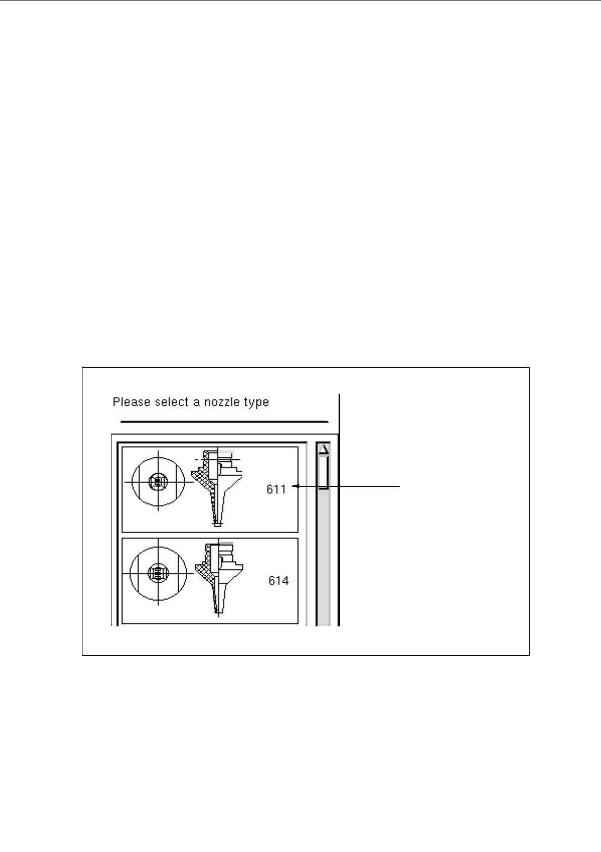
The selection window containing a list of all defined types of the selected tool type is opened.
Fig. 6.1.13 Selection Window of the "Nozzle Type"
nozzle type
User’s Manual Line Computer UNIX 6 Product / Package Form
Software Version 402.xx Edition 03/97 6.1 Package Form Editor
6 - 31
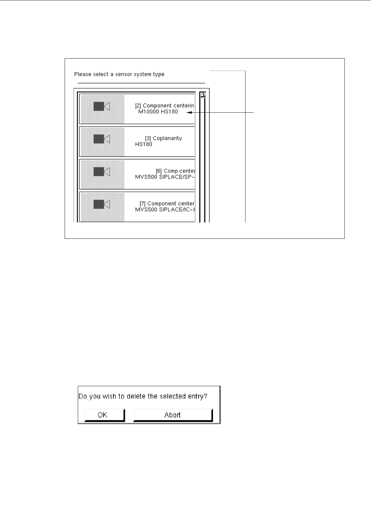
Fig. 6.1.14 Selection Window of the "Sensor Type"
●
Click on desired type.
The selection window is closed. The symbol of the selected tool type together with the number of
the created tool type is displayed in the display area of the main window.
-
Deleting
An existing tool can be deleted.
●
Click on button of the desired tool type.
All existing tools of the selected type are displayed.
●
Select tool from the display area.
●
Click on
Delete
.
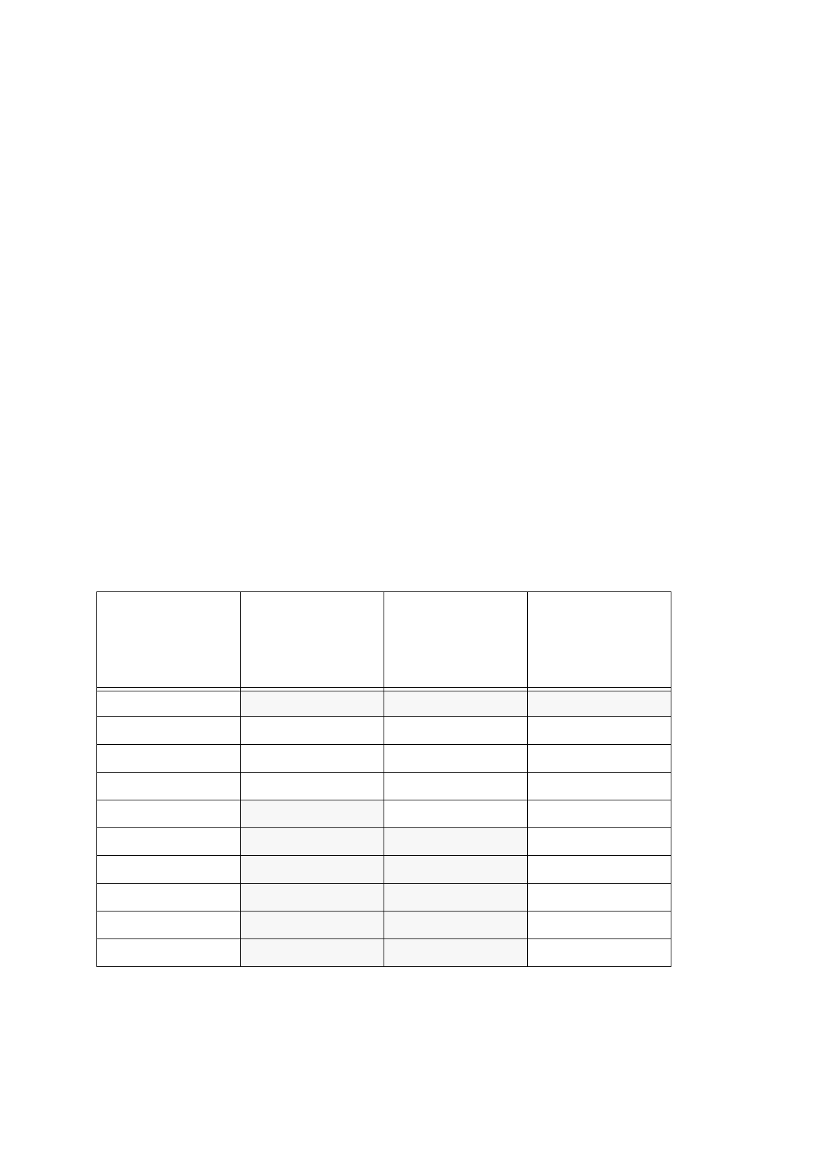
The following dialog box is opened.
●
Click on
OK
in the dialog box.
The dialog box is closed.
The symbol of the selected tool is no longer displayed in the display area.
sensor type
6 Product / Package Form User’s Manual Line Computer UNIX
6.1 Package Form Editor Software Version 402.xx Edition 03/97
6 - 32
6.1.2.11 Package Form Editor Editing Fields - "Handling data" Display
Editing field "Handling values"
-
Placing force Here, as a preset value for the force, a value between 1 and 10
is to be entered, which is then converted into the actual place-
ment force (see Table below).
The setting of the force that is used to place the nozzle on the
component and the component on the board depends on the
following parameters:
Material of the component package
Component size
Composition (consistency) of the adhesive or solder paste
The Table below shows the conversion of the value entered (force presetting) into the value of actual
placement force appropriate for the respective placement head type and the nozzles used.
If the preset value lies, however, below or above the acceptable force setting range, the minimum or
maximum placement force, respectively, will be used for the head type in question (see the shaded
cells).
Value entered
[
N]
(force presetting)
Actual placement
force
[
N]
for
revolver head
with 3xx or 6xx type
nozzles
Actual placement
force
[
N]
for
revolver head
with 7xx type
nozzles
Actual placement
force
[
N]
for
IC-head with 4xx
type nozzle
1
2,4 2,4 1,3
22,42,42
3333
4444
5
455
6
4 56
7
4 57
8 4 58
9
4 59
10
4 510
Tab. 6.1 - 1 Placement Forces