00190802-02.pdf - 第253页
User’s Manual Line Computer UNIX 8 Product / PCB Software Version 402.xx Edition 06/96 8.1 PCB Editor 8 - 35 8.1.6. 1 EDIT ME NU - Resetting Placement P osit ion data The en trie s alrea dy e xisti ng f or the P CB ty pe…

8 Product / PCB User’s Manual Line Computer UNIX
8.1 PCB Editor Software Version 402.xx Edition 06/96
8 - 34
The window of the Placement Position Editor is subdivided as follows:
-
Menu bar
-
Display area
-
Editing area
-
Command area
Menu Bar
The menu bar contains the menus "FILE", "EDIT", "SERVICES" and "HELP".
The "EDIT" menu is described in detail in section 8.1.6.1 and the "SERVICES" menu is described in section
8.1.6.2.
☞
NOTE
Since the functions and operation of the "FILE" and "HELP" menus are similar to those in other application
programs of the line computer, they are described comprehensively in chapter 2.
Editing area
(see section 8.1.6.3)
For each PCB type selected in the Structure Editor a placement program can be created in the editing area of
the Placement Position Editor window (see Fig. 8.1.11). Such a program contains the positions of the
components to be placed (with reference to the PCB zero point, see Fig. 8.1.3) as well as the fiducial sets that
may be required for component position recognition.
A completed placement program can also be adopted by another PCB type or modified, if required. Moreover,
it is possible to copy only those parts of a placement program that are required for a different PCB type.
Command area
(see section 8.1.6.4)
In this area the buttons "Check pl. pos." and "Search/Replace" are located. By means of these buttons the
entered placement position data can be reviewed, searched and replaced, if required.
User’s Manual Line Computer UNIX 8 Product / PCB
Software Version 402.xx Edition 06/96 8.1 PCB Editor
8 - 35
8.1.6.1 EDIT MENU
-
Resetting Placement Position data
The entries already existing for the PCB type concerned can be deleted from the editing area.
●
Click on EDIT --> Reset placement position.
The editing area is empty, new entries can be made.
☞
NOTE
If the PCB Editor is exited from without activating "Save" (in the Structure Editor), the old data will be
displayed again when the Placement Position Editor is called up.
-
Loading placement position of an existing PCB type
This function enables a placement program of another PCB type to be loaded into the Placement
Position Editor of the current PCB type.
●
Activate icon in the current window.
●
Select partial PCB structure (target).
●
Click on SERVICES --> Placement Position Editor.
The FSB for the selection of the (source) PCB is opened (see page 8 - 6).
●
Select PCB by double-clicking.
The main window of the new Structure Editor is opened.
●
Click on the partial PCB structure containing the PP data to be copied (source).
●
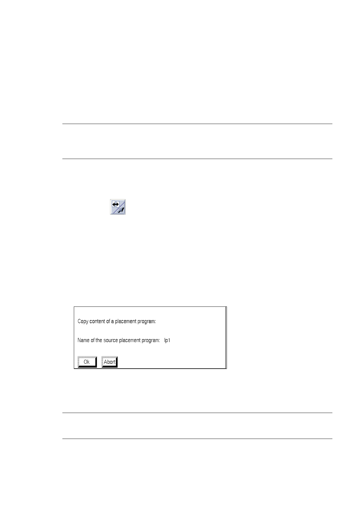
Activate EDIT --> Load placement position from in the current Placement Position Editor (target).
The following dialog box appears:
●
Confirm dialog box with OK .
The loaded placement program is displayed in the window of the Placement Position Editor.
☞
NOTE
If data had already been entered in the editing area, these will be replaced with the copied data.

8 Product / PCB User’s Manual Line Computer UNIX
8.1 PCB Editor Software Version 402.xx Edition 06/96
8 - 36
-
Mirror-inverting PP positions about the x-axis
The signs of all values entered in the editing area under "Y" (placement positions in y-direction) are
reversed.
●
Click on
EDIT
-->
Mirror-inverting placement positions about the X-axis.
All positive values entered (prior to the above clicking action) under "Y" are now displayed with a
negative sign preceding the entries, all previous negative values are now displayed as positive values.
-
Mirror-inverting PP positions about the Y-axis
The signs of all values entered in the editing area under "X" (placement positions in x-direction) are
reversed.
●
Click on
EDIT
-->
Mirror-inverting placement positions about the Y-axis.
8.1.6.2 SERVICES Menu
-
Opening the
Cluster Editor
●
Click on
SERVICES
-->
Cluster Editor
.
The window of the Cluster Editor is opened (see Fig. 8.1.8).
-
Opening new
Structure Editor
●
Click on
SERVICES
-->
Structure Editor...
.
The FSB for the selection of a new PCB is opened (see page 8 - 6).
●
Select PCB and confirm with
OK
.
The structure of the selected PCB is displayed in the display area of the newly opened window.
8.1.6.3 Editing Area of the Placement Position Editor
INPUT POSSIBILITIES:
-
Comp. name
name of the component (max. 11 characters)
-
X, Y
placement position in x and y-directions (referred to the PCB zero point);
it is possible to enter 3 decimal places before and 3 decimal places behind
the decimal point.
-
angle
angle at which component is placed during placement operation (-360° to
+360°) referred to the PCB coordinate system; it is possible to enter 3
decimal places before and 2 decimal places behind the decimal point.
-
bkdns
scheduling the processing sequence (process-specific data); b = placing,
k = gluing, d = dispensing (solder paste metering), n = reworking,
s = blocking (excluded from placement operation)