00190802-02.pdf - 第449页
User’s Manual Line Computer UNIX 14 Control / Control Modules Software Version 402.xx Edition 06/96 14.5 Set-Up Modification Generator 14 - 47 ● Sele ct set- up "xx.AR" by doub le-clic king. The FSB is closed a…
14 Control / Control Modules User’s Manual Line Computer UNIX
14.5 Set-Up Modification Generator Software Version 402.xx Edition 06/96
14 - 46
-
Display set-up
This option enables the operator to have a selected set-up displayed and printed out, if necessary.
●
Click on button
Display set-up
.
The selection window is closed and the main window of the Set-Up Modification Generator
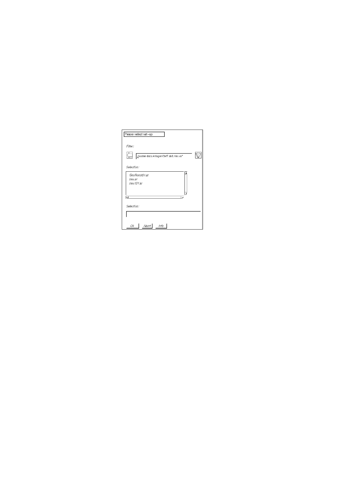
together with the FSB for the selection of the set-up, which is located above it, is opened.
●
Open the directory "*master data:Anlagen" by double-clicking.
●
Successively select line "*xx.ak" and subline "*xx.va" by double-clicking.
All previously defined set-ups are displayed in the FSB.
●
Select set-up "xx.ar" by double-clicking.
The FSB is closed and the main window of the Set-Up Modification Generator is displayed on the
screen. In the display area of the main window (see Fig. 14.5.2) the set-up for the station selected
from the selection field "Stations" is displayed.
-
Display PCB-specific part of set-up
This option enables the operator to display the set-up for a given PCB type and print it out, if
necessary.
●
Click on button
Display PCB-specific part of set-up
.
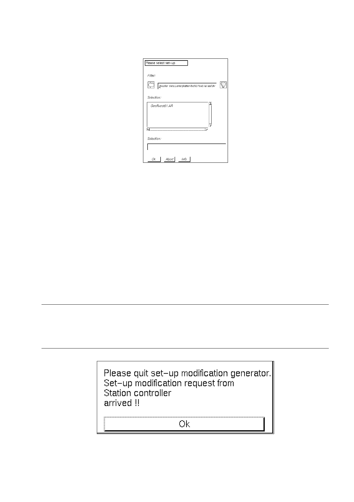
The selection window is closed and the main window of the Set-Up Modification Generator
together with the FSB for the selection of the PCB, which is located above it, is opened.
●
Open the directory "*master data:Leiterplatten" by double-clicking.
●
Successively select the PCB "*xx.la", "*.ad", line "*xx.AK" and subline "*xx.VA" by double-clicking.
A list of the set-ups that can be chosen for the selected PCB type is displayed in the FSB.
User’s Manual Line Computer UNIX 14 Control / Control Modules
Software Version 402.xx Edition 06/96 14.5 Set-Up Modification Generator
14 - 47
●
Select set-up "xx.AR" by double-clicking.
The FSB is closed and the main window of the Set-Up Modification Generator is displayed on the
screen. In the display area of the main window the set-up portion of the selected PCB type for the
station selected from the selection field "Stations" is displayed (see Fig. 14.5.2).
14.5.4 Main Window of Set-Up Modification Generator
The main window is opened upon each selection made in the selection window of the Set-Up Modification
Generator, or, for example, through a station controller if a changeover from the current set-up (initial set-up)
to a follow-up set-up is required for the processing of the PCB scheduled for production.
The main window provides the operator, for example, with the data of the initial set-up and the instructions for
the changeover to a follow-up set-up of a selected station.
☞
NOTE
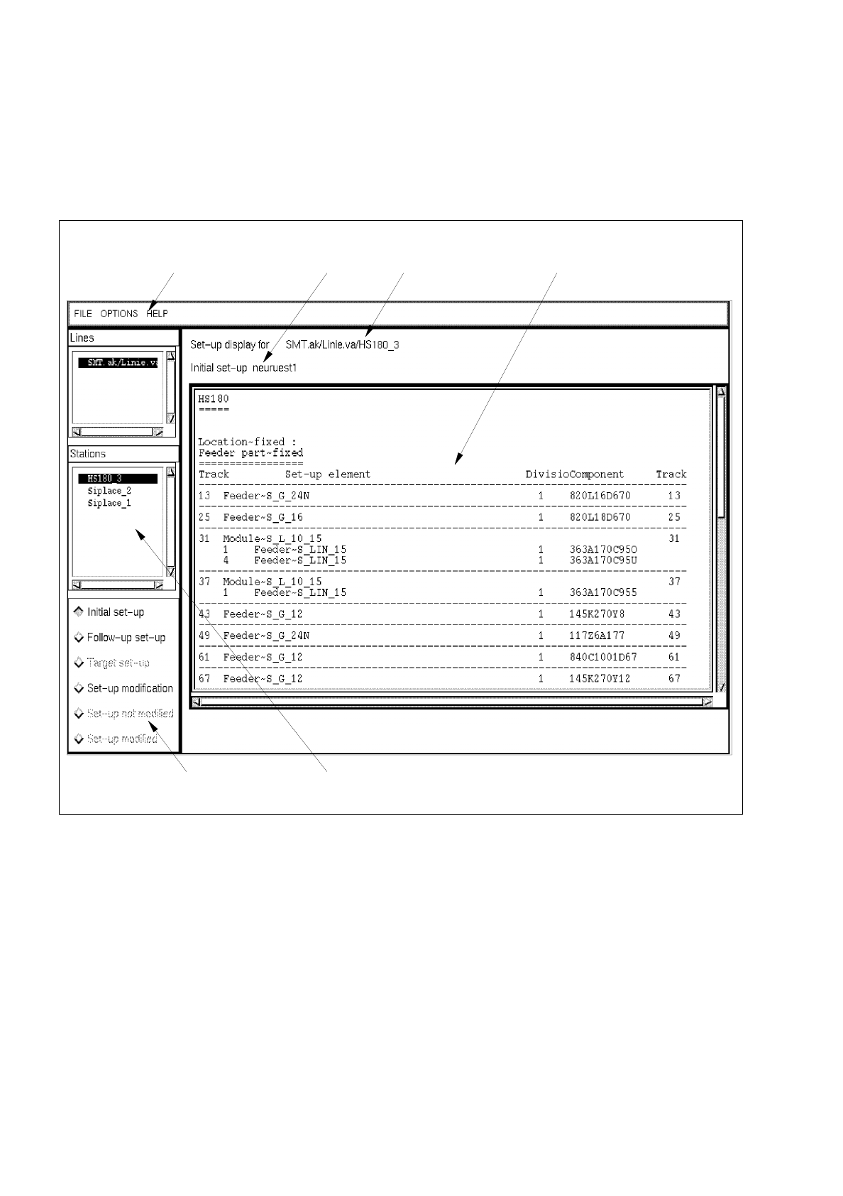
In the case that a changeover request - initiated by a requesting program, e.g. the Job Control (see section
14.2) is received after the main window of the Set-Up Modification Generator has been opened by the
operator, the station controller's changeover request is given priority. The following dialog box is displayed.
14 Control / Control Modules User’s Manual Line Computer UNIX
14.5 Set-Up Modification Generator Software Version 402.xx Edition 06/96
14 - 48
●
Confirm dialog box with
Ok
.
●
Exit from the Set-Up Modification Generator via the menu by selecting
Quit
.
The Set-Up Modification Generator opened by the operator is closed and only the Set-Up
Modification Generator opened by the station controller is displayed as the topmost window.
Fig. 14.5.2 Main Window of the Set-Up Modification Generator
In the following, the different areas of the main window of the Set-Up Modification Generator and their functions
are explained.
The main window is subdivided as follows:
-
Menu bar
-
Message and status line
-
Selection fields "Sublines" and "Stations"
-
Command area
-
Display area
selection field "Stations" command area
menu bar message line status line display area