00190802-02.pdf - 第98页
3 Desktop (Root Window) User’s Manu al Line Computer UNIX 3.2 Desktop User Interface Software Version 402.xx Edition 03/97 3 - 16 3.2. 1.3 SER VICES Menu - Equipment Ser ves to open the user interface of the Pr int an d …
User’s Manual Line Computer UNIX 3 Desktop (Root Window)
Software Version 402.xx Edition 03/97 3.2 Desktop User Interface
3 - 15
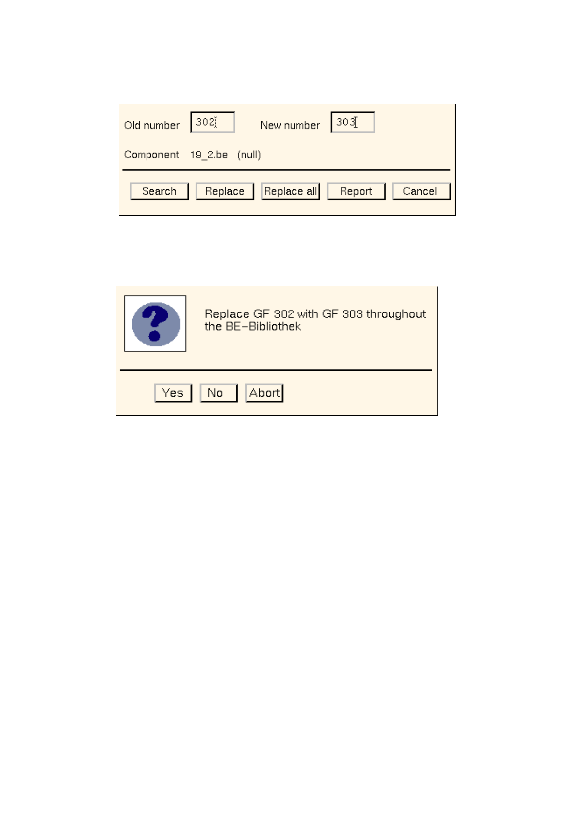
Or else:
●
Click on the
Replace all
button.
The following dialog box opens.
●
Click on
No
or
Abort
if the action displayed in the dialog box is not to be executed.
●
Click on
Yes
if the action displayed in the dialog box is to be executed.
From the currently found occurrence of the component (component file) onwards, the old GF
number will be replaced with the new GF number in all subsequently found occurrences of the
component (component files).
The
Report
button in the dialog box can be used to display the results of the action.
●
Click on
Report
in the dialog box.
The File Display main window opens.
●
For details on how to continue, refer to page 3 - 13.
●
When all desired replacements have been made, click on
Cancel
in the dialog box.
The window closes.

3 Desktop (Root Window) User’s Manual Line Computer UNIX
3.2 Desktop User Interface Software Version 402.xx Edition 03/97
3 - 16
3.2.1.3 SERVICES Menu
-
Equipment
Serves to open the user interface of the Print and Update Server. It basically serves to manage the dif-
ferent devices. The devices available in the LC system such as printers, diskette and tape drives can
be logged on (activated) or logged off (deactivated).
In addition, it is possible to intitiate the formatting of data carriers from the user interface.
●
Click on SERVICES --> Equipment.
The user interface of the Print and Update Server is opened (see chapt. 4).
-
Station configuration
Serves to open the user interface of the Configuration Editor. The configuration of a selected station
can be defined with the aid of the editor.
●
Click on SERVICES --> Station configuration.
The FSB containing the directory "Master data: Stationen" is opened.
●
Open the directory "Master data: Stationen" by double-clicking.
The list of the configured stations is displayed in the FSB.
●
Select the desired station by double-clicking.
The user interface of the Configuration Editor is opened (see chapt. 12, section 12.1).
-
Data Storage
This option causes the window for switching the file access mode to central or local data storage to be
opened.
●
Click on SERVICES --> Data storage.
The window for switching between the two file access modes is opened (see chapt. 4).
-
Line Configuration
This option is used to open the window for the line configuration. Using the appropriate buttons in
this window, the Line Editor for the configuration of a line or subline can be opened, or the FSB for
the selection of a different production line.
●
Click on SERVICES --> Line configuration.
The "Line configuration" selection window opens.
●
Click, for example, on the Line configuration button.
The FSB containing the "Master data: Anlagen" directory opens.
Select the desired line by double-clicking.
The user interface of the Line Editor for the configuration of the line opens (see chapt. 12,
section 12.2).
-
Line control
Serves to open the user interface of the line control.It enables the user to control the entire line. He
can start and stop the line, disable or enable the input conveyor, enter the conveyor width, reset the
entire line to the initial state (Reset), specify barcode and production strategies.
●
Click on SERVICES --> Line control.
The user interface of the line control is opened (see chapt. 14).

User’s Manual Line Computer UNIX 3 Desktop (Root Window)
Software Version 402.xx Edition 03/97 3.2 Desktop User Interface
3 - 17
3.2.1.4 PRODUCT Menu
-
Component Editor
Serves to open the user interface of the Component Editor. The Component Editor allows the user to
completely describe components in their electrical characteristics.
●
Click on PRODUCT --> Component Editor.
The FSB containing the file selection of all already-defined components is opened.
☞
NOTE The further procedure to be followed is described in chapt. 5.
-
Package Form Editor
Serves to open the user interface of the Package Form Editor. The Package Form Editor allows the
user to completely describe components in their geometrical characteristics.
●
Click on PRODUCT --> Package Form Editor.
The FSB containing the file selection of all already-defined package forms is opened.
☞
NOTE The further procedure to be followed is described in chapt. 6.
-
Adhesive Pattern Editor
Serves to open the user interface of the Adhesive Pattern Editor. The coordinates of adhesive dots for
adhesive patterns are defined in the Adhesive Pattern Editor. Due to the different adhesive patterns
available it can be ensured that components of various sizes can be securely attached to the PCBs
during production.
●
Click on PRODUCT --> Adhesive Pattern Editor.
The FSB containing the ".dm" file is opened. This file contains all already-defined adhesive
patterns.
●
Select the .dm adhesive pattern file by double-clicking.
The content of the ".dm" adhesive pattern file is displayed in an FSB.
☞
NOTE The further procedure to be followed is described in chapt. 7.
-
PCB Editor
Serves to open the user interface of the PCB Editor. The PCB Editor allows the user to completely
describe a PCB to be processed.
●
Click on PRODUCT --> PCB Editor.
The FSB containing the files of all already-defined PCBs is opened.
☞
NOTE The further procedure to be followed is described in chapt. 8.
-
CAD Import
This option is used to open the user interface of CAD Import. It enables the operator to easily adapt
placement files that were created on external systems to the SIPLACE format.
●
Click on PRODUCT --> CAD-Import.
The FSB containing all ".cad"-files stored in the CAD library opens.
☞
NOTE The further procedure to be followed is described in chapt. 4, section 4.6.