00190802-02.pdf - 第22页
1 Hardware / Software Installati o n User’s Manu al Line Computer UNIX 1.2 Hardware Installation Software Version 402.xx Edition 06/ 96 1 - 8 6 Pictur e heigh t (V-S ize) Serves to chang e the pi cture he ight. 7 Pictur …
User’s Manual Line Computer UNIX 1 Hardware / Software Installation
Software Version 402.xx Edition 06/96 1.2 Hardware Installation
1 - 7
1.2.3 Monitor - Type SIPLACE 17" FLEXSCAN
1.2.3.1 Connections and Settings
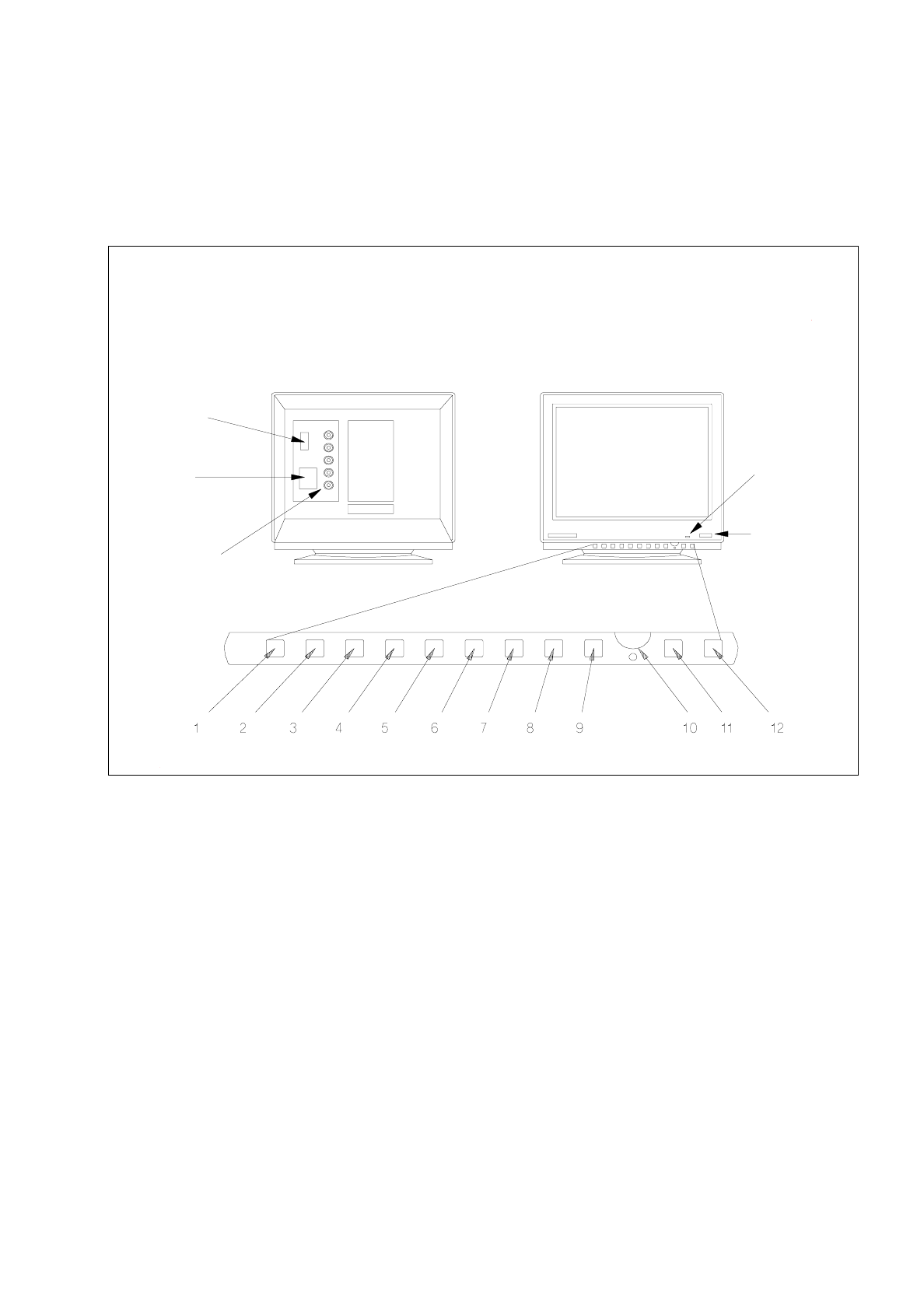
Fig. 1.2.3 Monitor - connections, control elements, setting elements
1 Function key
This key can be used to reset any adjustments made in the factory.
2 Trapezium distortion
Serves to correct any trapezium distortion so as to obtain a recatangular display area.
3 Pin-cushion distortion
The pin-cushion distortion at the left and right edge of the screen can be reduced to a minimum using
this button.
4 Vertical screen position (V-Position)
Use this control to optimally position the display vertically.
5 Horizontal screen position (H-Position)
Use this control to optimally position the display horizontally.
power
indicator lamp
power switch
video interface
(connection to
computer)
power
connection
signal inputs
(BNC connections)
rear view front view

1 Hardware / Software Installation User’s Manual Line Computer UNIX
1.2 Hardware Installation Software Version 402.xx Edition 06/96
1 - 8
6
Picture height (V-Size)
Serves to change the picture height.
7
Picture width (H-Size)
Use this control to adjust the picture width.
8
Brightness
The brightness is to be so adjusted that also dark grey scales can be clearly distinguished.
9
Save Button
Use this button to store the adjustments you may have made. If this button is not pressed, no storing
will take place.
10
Adjustment control
This control is used to adjust the functions selected via the buttons. If no selections have been made
this control is used for adjusing the contrast.
11
D-SUB/BNC button
Use this button to select the active video input, i.e. D-SUB or BNC.
The green LED is illuminated if BNC input is active.
12
Demagnetizing switch
Use this switch if color spots or slight misconvergences appear on the screen.
User’s Manual Line Computer UNIX 1 Hardware / Software Installation
Software Version 402.xx Edition 06/96 1.2 Hardware Installation
1 - 9
1.2.4 Monitor - Type MCM 1702 17" MULTISCAN
1.2.4.1 Connections and Settings
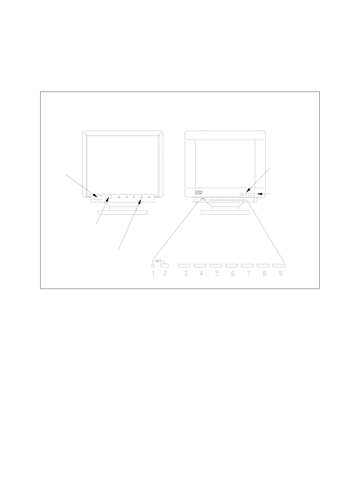
Fig. 1.2.4 Monitor - connections, control elements, setting elements
The controls to adjust the screen display have different functions depending upon the operating mode currently
used. These functions are represented by symbols provided above and below the controls. The MODE button
is used to switch between the functions assigned to the controls. Controls 3 to 9 have two functions in every
operating mode. The corresponding function can be activated depending upon whether the right or left side of
the button is pressed (see description below).
1 Mode indicator
When the mode indicator is switched off, the functions of the buttons of the control panel correspond to
those functions represented by the symbols underneath the buttons.
2 MODE
This button serves to switch between the different functions assigned to the individual controls.
●
Press the MODE button. The functions of the controls are switched to those symbolized
above or below the buttons.
Rear
Front
video interface
(connection to
computer)
signal inputs
(BNC connections)
power
power
power switch
indicator lamp
connection