00190802-02.pdf - 第185页
User’s Manual Line Computer UNIX 6 Product / Package Form Software Version 402.xx Edition 03/97 6.1 Package Form Editor 6 - 11 Editing field "Packa ging tolerance" - X [mm] m ax. per mis sible position al tol e…

6 Product / Package Form User’s Manual Line Computer UNIX
6.1 Package Form Editor Software Version 402.xx Edition 03/97
6 - 10
-
Pin/Ball
This command permits the window for the description of the model data for a selected object
(pin/ball) to be opened.
●
From the view area select the group containing the object (pin/ball) whose model data you wish to
edit.
The selected group is surrounded by a rectangle.
●
Click on
Pin/Ball
.
The window for the description of the model data is displayed on the screen (see Fig. 6.1.8 or
Fig. 6.1.12).
6.1.2.5 Package Form Editor Editing Fields - Setting "Vision data"
☞
NOTE
When an existing GF-file is opened upon the start-up of the Package Form Editor, the factory or customer
defined default values are contained in the editing fields described below.
Editing field "Nominal dimensions"
-
X +/-
[mm] component length, with indication of the tolerances
see Fig. 6.1.5 or Fig. 6.1.9
-
Y +/-
[mm] component width, with indication of the tolerances
see Fig. 6.1.5 or Fig. 6.1.9
-
Z +/-
[mm] component height, with indication of the tolerances
see Fig. 6.1.6 or Fig. 6.1.9
☞
NOTE
The length of a component refers to the x-direction and its width to the y-direction since the position of the
component (in the Vision System) is so defined that "pin 1" is located at the bottom on the left (see Fig.
6.1.5 and Fig. 6.1.9).
Editing Area "Body"
☞
NOTE
This field is not
displayed if the current package form type is a "PDC" (see Fig. 6.1.2) or a "BGA" (see Fig.
6.1.3) since with these types the dimensions of the package body correspond to the nominal dimensions.
-
X
[mm] length of package body (see Fig. 6.1.6)
-
Y
[mm] width of package body (see Fig. 6.1.6)
User’s Manual Line Computer UNIX 6 Product / Package Form
Software Version 402.xx Edition 03/97 6.1 Package Form Editor
6 - 11
Editing field "Packaging tolerance"
-
X
[mm] max. permissible positional tolerance of the component in the
package in x-direction
-
Y
[mm] max. permissible positional tolerance of the component in the
package in y-direction
-
Angle
[Degree] max. permissible deviation from the 0-degree position of the
component (rotational angle in the package)
Editing field "Acceptance limits" (only FDC and BGA)
☞
NOTE
When the Package Form Editor is opened for a new package form, the editing fields of this area already
contain the default values for the spacing and row tolerances.
In the case of the "BGA" package form type (see Fig. 6.1.3) only the "Spacing" editing field is available.
-
Spacing
[mm] Max. permissible value for pin spacing deviation
(spacing ^
distance between pin(ball) centers)
If the value for the pin spacing error limit is exceeded (i.e. the
leads of an "FDC" are bent at the sides)
the component is identified as defective by the Vision System
and excluded from the placement program.
-
Row
[mm] Max. permissible offset of opposite identical rows of
a "FDC" (i.e., max. permissible symmetric deviation)
-
Cubic component
[mm] Description see section 6.1.2.3
☞
NOTE
When the Package Form Editor is opened for the definition of a new package form, the editing fields
"Nominal dimensions" and "Packaging tolerance" are blank, only the editing area "Acceptance limits"
already contains the default values".
6 Product / Package Form User’s Manual Line Computer UNIX
6.1 Package Form Editor Software Version 402.xx Edition 03/97
6 - 12
Procedure to be followed for editing package form data:
Editing new GF-data:
●
Click on editing field "X" in the "Nominal dimensions" editing area, enter value and complete the
entry with RETURN.
●
Click on editing field "Y", enter value and complete the entry with RETURN.
In the editing fields for the width and length tolerances, and in the "Packaging tolerance" editing
area the automatically calculated default values are displayed.
●
Click on editing field "Z", enter value and complete entry with RETURN.
In the editing field for the height tolerance the automatically calculated default value is displayed.
☞
NOTE
The default values derived from the values entered will only be computed if each entry is
completed by pressing RETURN.
●
Click on editing field "X" in the "Body" editing area, enter value and complete the entry with
RETURN.
●
Click on editing field "Y", enter value and complete the entry with RETURN.
Changing existing data:
●
Click on desired editing field (position cursor in front of the value).
●
Delete value using the DELETE key.
●
Enter new value and complete the entry by pressing RETURN.
☞
NOTE
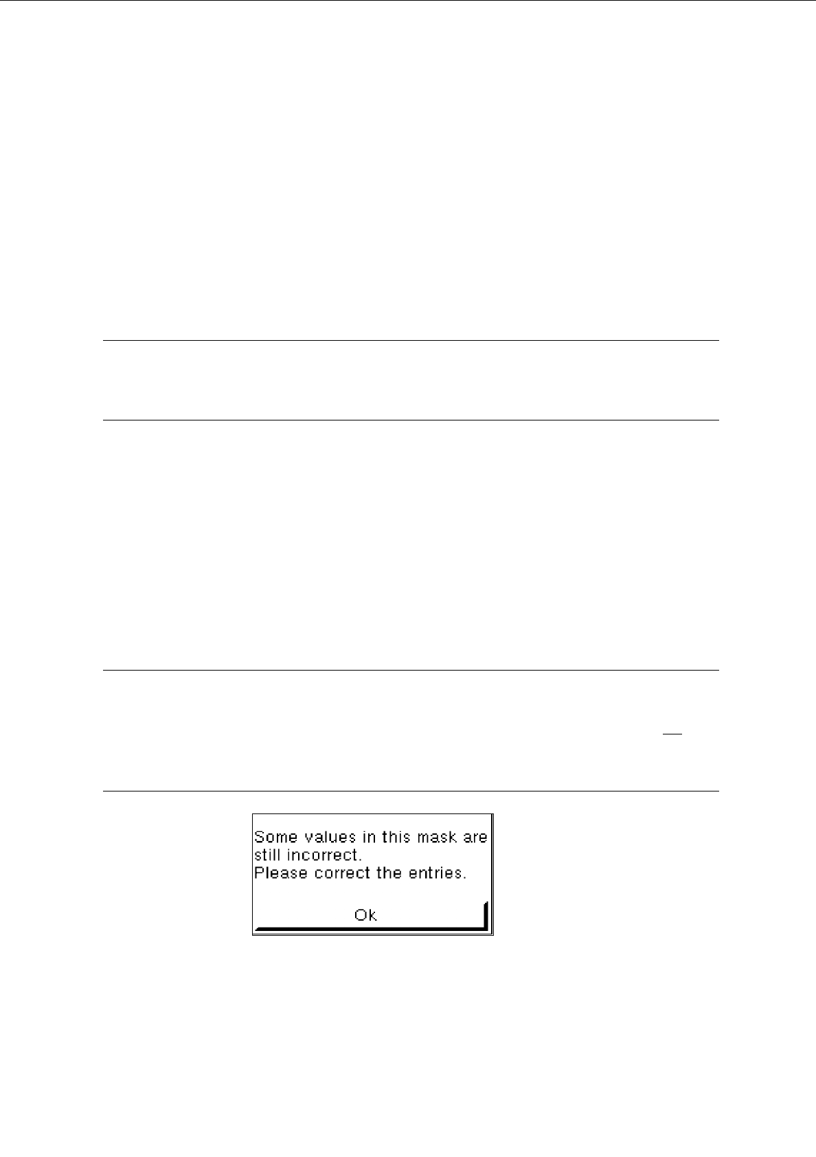
If invalid values or characters (e.g. letters or a comma as decimal point) were entered, the field being
edited is surrounded by a red frame and the entry must be corrected. If the RETURN key is not
pres-
sed after each entry, faulty fields will not be shown in a red frame until the GF-file is saved , and the
following dialog box will be opened:
●
Close dialog box by selecting
OK
and correct the faulty entries.