80S-20贴片机.pdf - 第102页
4 Power Supply SIPLACE 80S-20/F4 Service Manual 4.3 Control Unit Edition 01/96 4 - 16 Fig. 4.3.1 Control unit - partial view of the front with power supp ly unit T o mak e measureme nts at the back of the c ontrol u nit …

SIPLACE 80S-20/F4 Service Manual 4 Power Supply
Edition 01/96 4.3 Control Unit
4 - 15
4.3 Control Unit
4.3.1 General
The control unit is located at the back of the SIPLACE machine in the machine base (see Fig. 4.1.1).
● Open the metal door of the control unit.
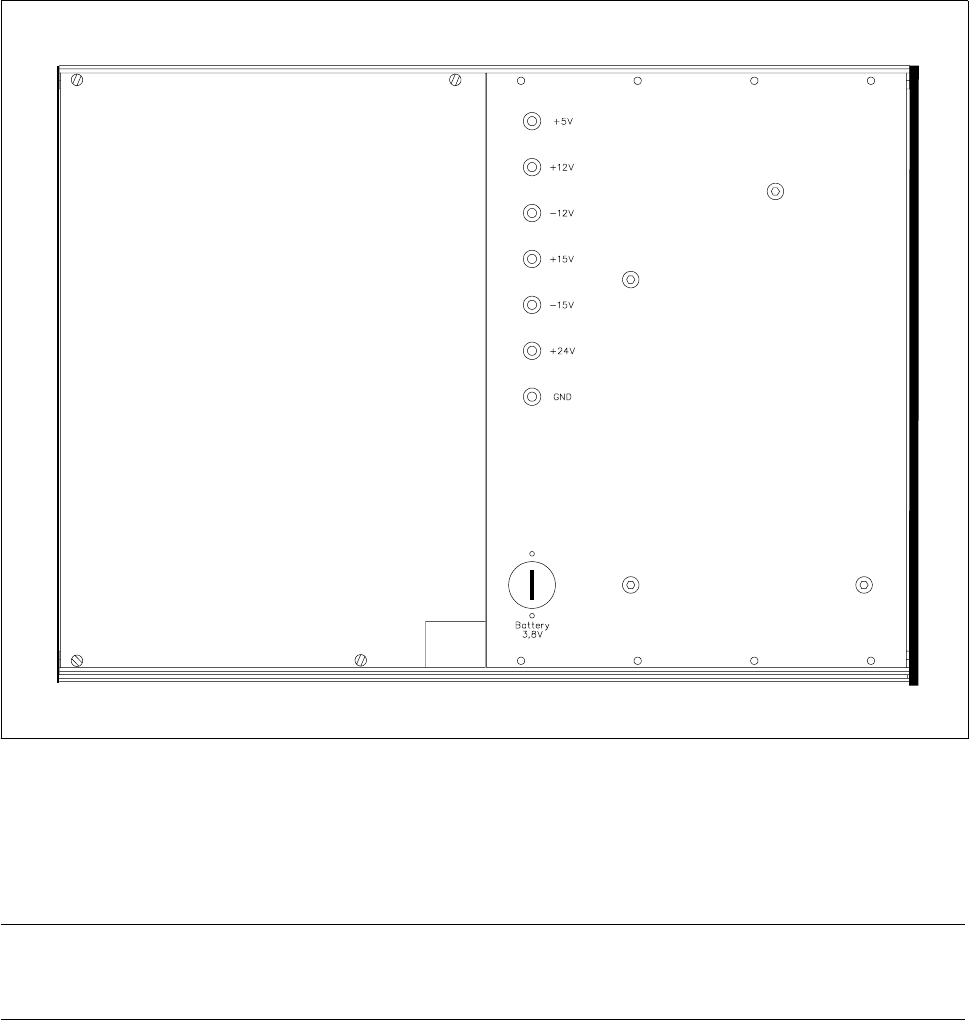
● In the top part of the control unit you will find power supply unit A26 with the associated voltage measure-
ment sockets (see Fig. 4.3.1).
4.3.2 Supply Voltages
● Switch the main switch of the machine on.
Power supply unit A26 supplies these direct voltages: + 5 V, + 12 V, – 12 V, + 15 V, – 15 V and 24 V.
● At the voltage measurement sockets measure the direct voltages listed here (see Fig. 4.3.1).
Fuse F1 is located in power supply unit A26 and protects against overload the 5 V voltage supply which is
routed to the gantries via the ribbon cable.
F1 is a 3.15 A fuse. Use the digital ohmmeter to check whether the fuse is okay.
NOTE
If automatic circuit-breaker F1 is defective this may result in faults in the limit switch loops (limit switch acti-
vated). When making detailed measurements or carrying out fault location in the terminal rails or circuits you
should refer to the relevant circuit diagrams.
4 Power Supply SIPLACE 80S-20/F4 Service Manual
4.3 Control Unit Edition 01/96
4 - 16
Fig. 4.3.1 Control unit - partial view of the front with power supply unit
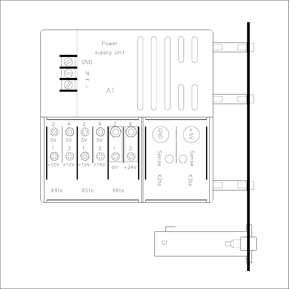
To make measurements at the back of the control unit proceed as follows:
● Switch the placement machine off and disconnect it from the power supply.
● Undo the retaining screw of the control unit and pull out the control unit.
CAUTION
Q
Make sure you do not damage the cable or put tensile stress on the snap-in connections.
● If necessary, support the control unit on a stool.
● Reconnect the machine to the power supply. Switch it on and then carry out the measurements required
(see Fig. 4.3.2). You should comply with the safety instructions in Section 1.
SIPLACE 80S-20/F4 Service Manual 4 Power Supply
Edition 01/96 4.3 Control Unit
4 - 17
Fig. 4.3.2 Top view of the power supply unit in the control unit