80S-20贴片机.pdf - 第19页
SIPLACE 80S-20/F4/F4-6/F5 Serv ice Manual 1 Operational Safety Edition 04/98 1.1 Information on safety 1 - 9 1.1. 7 Sa fety in str uctions for th e PC B barc ode read er (op tion) Fig. 1.1.6 PCB barcode reader ( bottom) …
1 Operational Safety SIPLACE 80S-20/F4/F4-6/F5 Service Manual
1.1 Information on safety Edition 04/98
1 - 8
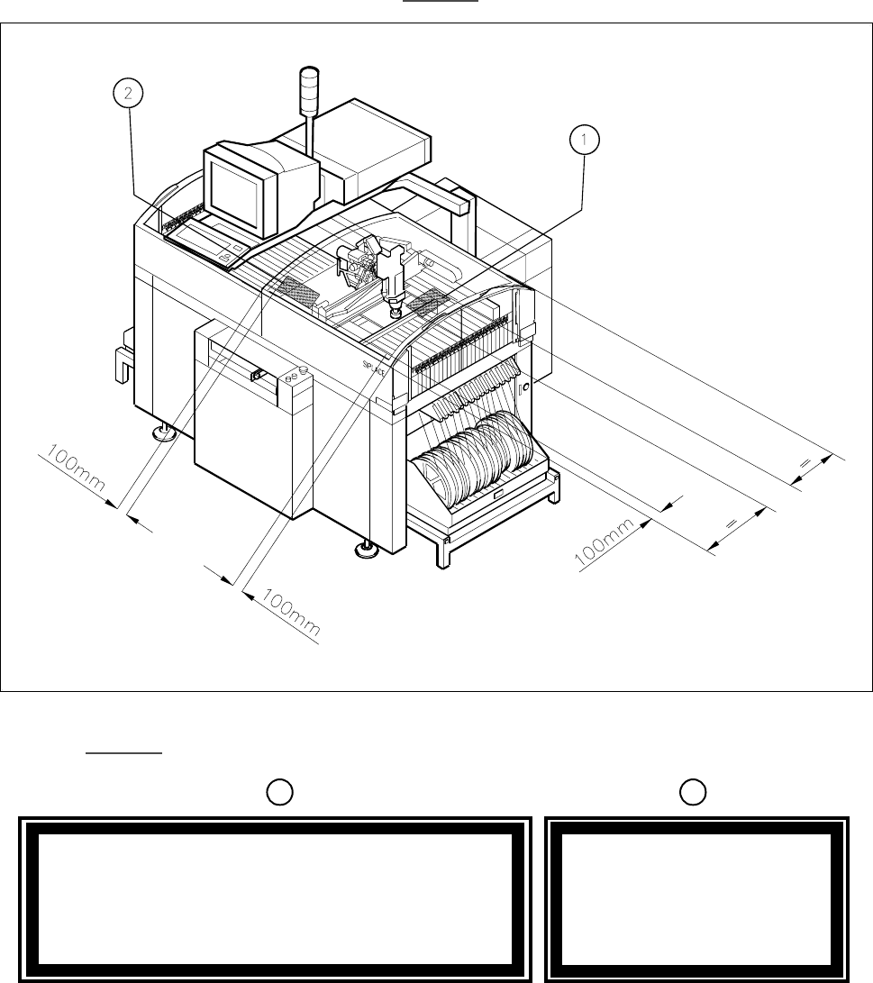
The illustration below shows the location of the safety information for operating the coplanarity laser module of
the SIPLACE 80F
4
, 80F
4
-6 or 80F
5
. This information must be glued onto the cover in the places which are
indicated by arrows so that it is clearly visible (see Fig. 1.1.5
).
Fig. 1.1.5 Safety instructions on the SIPLACE 80F
4
/ F
4
-6 / F
5
.H\WR )LJ
Caution
Invisible laser radiation if the cover is opened
and safety interlock is bypassed
Do not stand in front of the beam
LASER CLASS 1
1
2
SIPLACE 80S-20/F4/F4-6/F5 Service Manual 1 Operational Safety
Edition 04/98 1.1 Information on safety
1 - 9
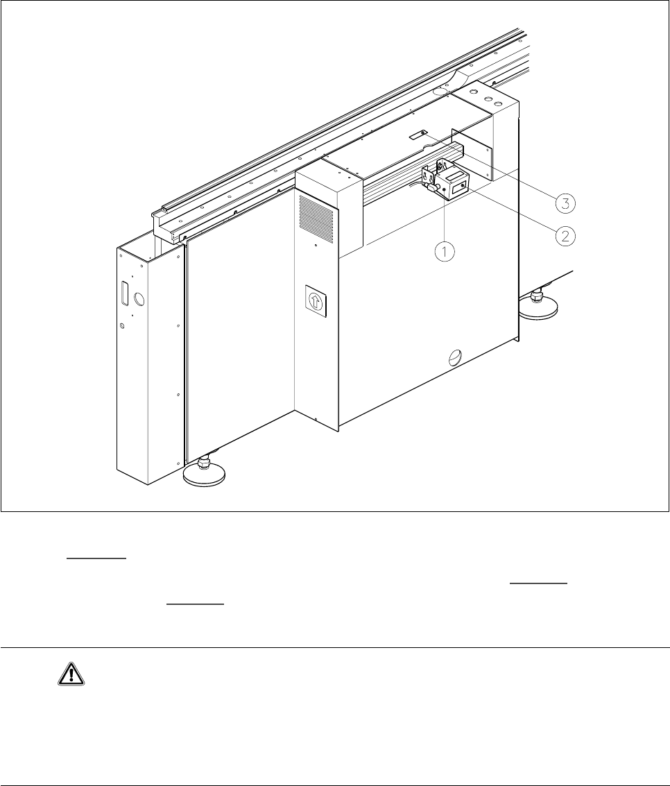
1.1.7 Safety instructions for the PCB barcode reader (option)
Fig. 1.1.6 PCB barcode reader (bottom)
.H\WR)LJ
1 PCB barcode reader (bottom) 2 Label: ’laser radiation...’ (Fig. 1.1.7)
3 Label: ’Caution ...’ (see Fig. 1.1.8
)
Caution
The radiant power of the barcode reader‘s scanning beam is less than 1mW. This means that the barcode
reader conforms to laser class 2 and, according to DIN EN 60825-1, requires no special safety equipment or
protective measures. NEVER look into the laser beam. There is also a safety circuit that switches off the laser
diode if the polygon wheel stops or turns too slowly.
1 Operational Safety SIPLACE 80S-20/F4/F4-6/F5 Service Manual
1.1 Information on safety Edition 04/98
1 - 10
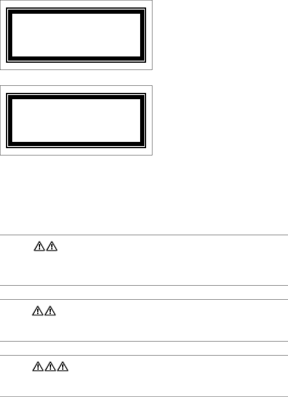
Fig. 1.1.7 Label: ‘Laser radiation...’
Fig. 1.1.8 Label: ’Caution ...’
1.1.8 Safety instructions for changing the component table
Changing the component table is described in section 10.3 “Component tables“. Always follow the following
safety instructions to prevent injury or damage to the automatic placement system.
WARNING
When you change the component table, always follow the sequence for removing the plugs from the commu-
nication unit and then connecting them again as described below. If you do not follow the specified order,
faults may occur in the component table.
WARNING
Move the portal out of the range of the component table over the PCB transport. This will prevent the possibil-
ity of a head crash.
DANGER
Press the emergency stop button. The gantry axes are switched off and isolated.
This will prevent the gantries starting up accidentally, thus preventing the associated risk of injury or damage.
Laser radiation
Do not look into the beam
Laser class 2
Caution
Laser radiation if the cover is opened
and the safety interlock is bypassed
Do not look into the beam