80S-20贴片机.pdf - 第266页
8 IC Head S IPLACE 80S-20/F4 Service Manual 8.2 Structure and Functional G roups of the IC Head Edition 01/97 8 - 4 6WUXFWX UHDQG)XQFWLRQDO* URXS VRIWKH,&+HDG 1 2 3 A 5 7 6 8 B 9 10 11 12 13 14 15 16 4
SIPLACE 80S-20/F4 Service Manual 8 IC Head
Edition 01/97 8.1 Position and Environment of the IC Head
8 - 3
3RVLWLRQDQG(QYLURQPHQWRIWKH,&+HDG
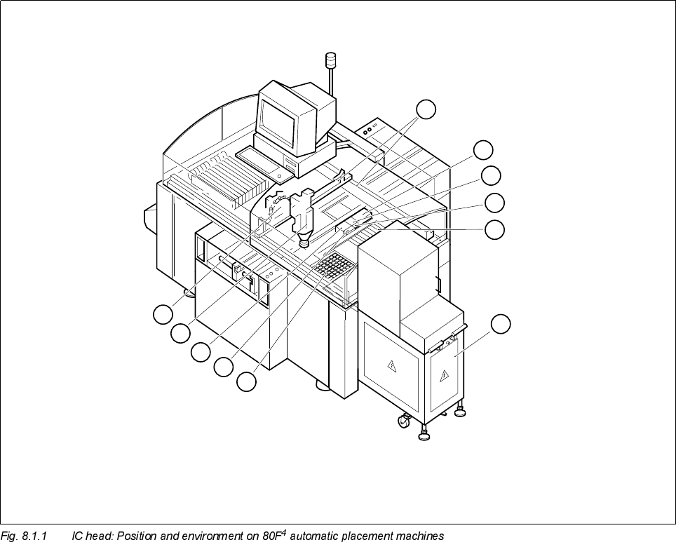
Key to Fig. 8.1.1
The SIPLACE 80F
4
automatic placement system is equipped with a revolver placement head and an IC
placement head. Both placement heads are mounted on a common gantry.
The IC head is fixed to the gantry with two M4 x 16 or M4 x 25 fillister head screws. Two parallel pins ensure
that the IC head is mounted precisely on the gantry.
1 IC head 2 Revolver head
3 X/Y gantry system (gantry 1) 4 Nozzle changer for IC head
5 Flip-chip camera (option) 6 Reject container for IC head
7 Location 2: feeder module 8 Wafflepack changer (option)
9 Location 1: wafflepack magazine for WPC 10 Coplanarity laser module (option)
11 IC camera
8
7
6
5
4
3
9
10
11
1
2
8 IC Head SIPLACE 80S-20/F4 Service Manual
8.2 Structure and Functional Groups of the IC Head Edition 01/97
8 - 4
6WUXFWXUHDQG)XQFWLRQDO*URXSVRIWKH,&+HDG
1
2
3
A
5
7
6
8
B
9
10
11
12
13
14
15
16
4
SIPLACE 80S-20/F4 Service Manual 8 IC Head
Edition 01/97 8.2 Structure and Functional Groups of the IC Head
8 - 5
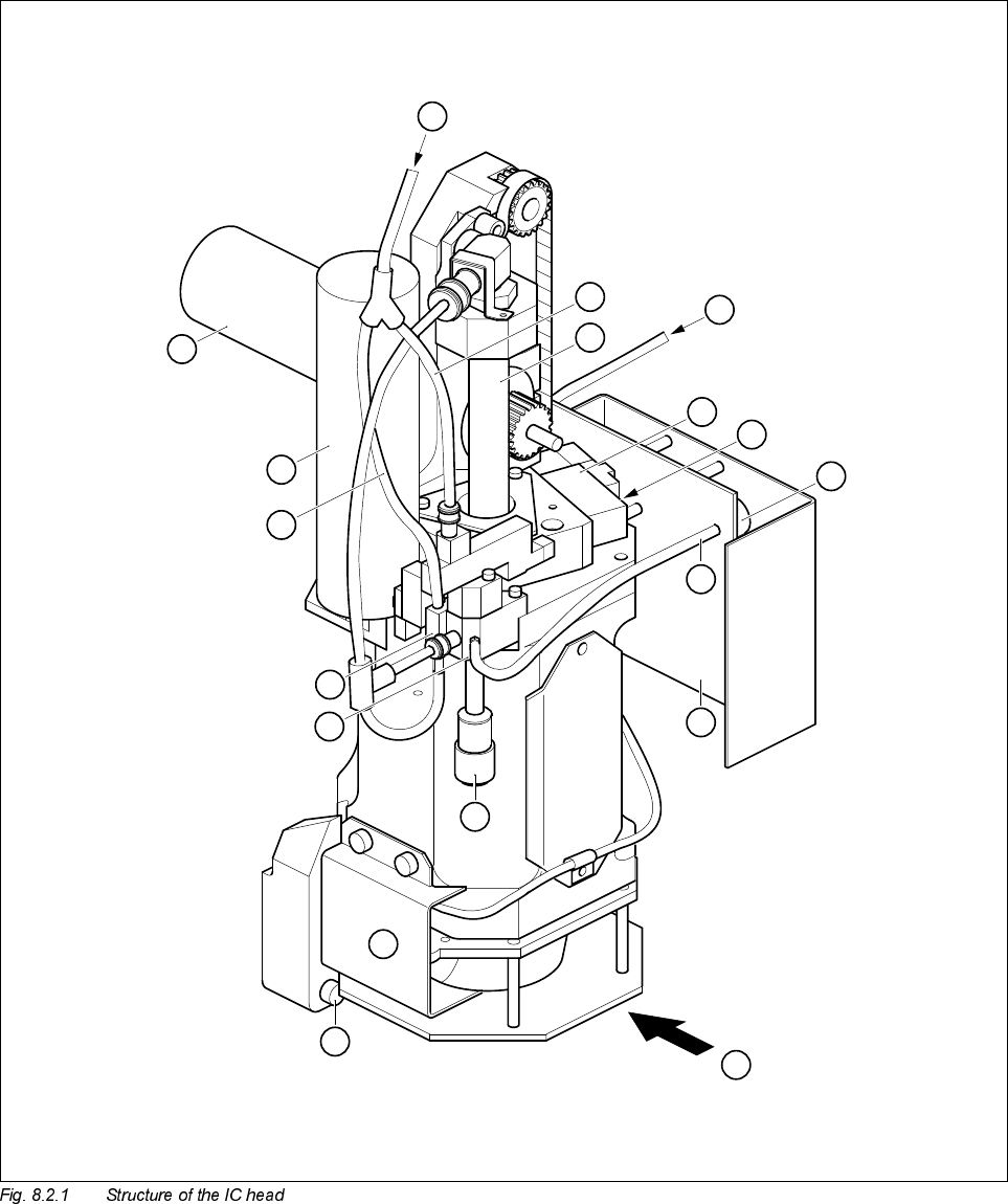
Key to Fig. 8.2.1
=D[LV
The z axis consists of the following principal components:
– Servo motor, tachogenerator and incremental encoder
– Synchroflex toothed belt
– Sleeve and
– End position BERO
The servo motor moves the sleeve in the vertical direction by means of the Synchroflex toothed belt. The res-
olution of the incremental position measurement is 27.7 digits per millimeter travel.The end position BERO
signals the upper sleeve position.
During the approach to the reference point, the z axis moves up to the upper stop, changes direction,
searches for the zero pulse and then moves to the 0 digit position by the amount indicated by the zero point
correction. The gantry axes must not start to move until
– the z axis is in the 0 digit position and
– the end position BERO has been activated.
'U$[LV
The dr axis consists of the following principal components:
– Servo motor with tachogenerator
– Pair of friction wheels
– Incremental encoder
The angular resolution of the dr axis is 72,000 digits per 360°, i.e. 1 digit corresponds to 1/200°.
1 Compressed air supply for vacuum generation 2 Sleeve (z axis)
3 2.3 ± 0.2 bar for opening the z axis clamping device 4 Solenoid valve for z axis clamping device
5 Vacuum sensor 6 Lead for vacuum sensor
7 IC head C0006 conversion board 8 Silencer
9 Fixing screw for IC head 10 Encoder for dr axis
11 Vacuum generator 12 ’Forced air’ solenoid valve
13 ’Forced air’ compressed air supply 14 Servo motor for dr axis
15 Servo motor for z axis
A Manual actuation of solenoid valve for
z axis clamping device
B Viewed in IC head mounting direction