80S-20贴片机.pdf - 第212页
7 Components Table SIPLACE 80 S-20/F4 Service Manual 7.1 Overview Edition 03/97 7 - 10
SIPLACE 80 S-20/F4 Service Manual 7 Components Table
Edition 03/97 7.1 Overview
7 - 9
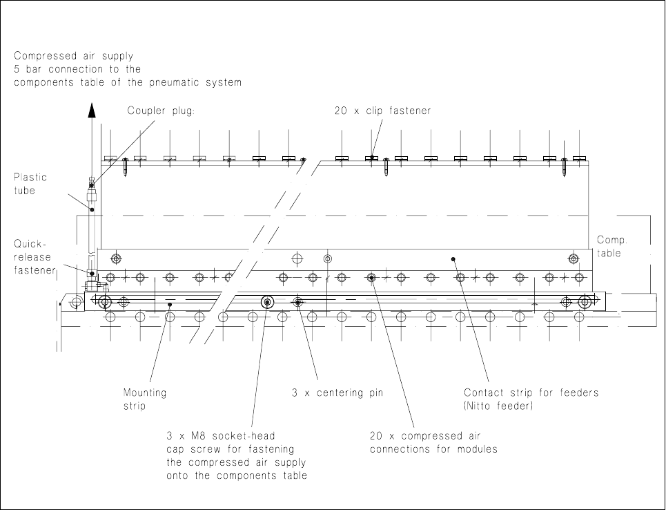
7.1.4 Components Table Compressed Air Supply Unit (Option)
Fig. 7.1.4 Components table compressed air supply , top view
When compressed air feeder modules (= feeder modules which operate using compressed air) are to be used
the optional "components table compressed air supply unit" (see diagram above) together with the "compo-
nents table pneumatic system" (see Fig. 7.1.4) is installed in the SIPLACE 80 S machine.
● This "components table compressed air supply unit" (= compressed air distributor strip) is fitted in a
defined position on the longer side of the changeover components table (see Fig. 7.1.2) by means of 3
centering pins and fastened down to the components table with 3 socket-head cap screws M8.
● Each compressed air feeder module after installation at the components table is attached to the com-
pressed air distributor strip by means of a clip fastener. When the module is used the corresponding
plunger is pressed downwards into the compressed air distributor strip which assures continuous availabil-
ity of compressed air at the module.
● Connection to the power supply is at the corresponding socket on the connections panel (communications
unit).
● Actuation of the solenoid valves in the feeder module operates the compressed air branch in the module
and the components are conveyed onwards, separated into singles and brought into the pick-up position.
7 Components Table SIPLACE 80 S-20/F4 Service Manual
7.1 Overview Edition 03/97
7 - 10

SIPLACE 80 S-20/F4 Service Manual 7 Components Table
Edition 03/97 7.2 Fault Characteristics
7 - 11
7.2 Fault Characteristics
Carry out preliminary fault location with the aid of fault characteristics listed below and their possible causes.
The order in which the possible causes are given here represents the best way of proceeding as far as the
amount of work and the probability of the fault are concerned.
For detailed information on further location and correction of the fault please refer to the corresponding sec-
tion of this Service Manual.
DANGER OOO
Please note with all fault correction work the safety instructions in the User Manual.
Please note in addition:
In the machine base interior the 400 VAC operating voltage is still present in certain modules even when the
main switch is switched off.
All work in the machine base interior must therefore only be carried out by authorized persons who have had
the appropriate training.
During all work in the machine base interior you must comply with the special VDE 0113 electrical safety reg-
ulations and disconnect the machine as soon as possible from the mains supply.
This also applies to all work on the power supply unit of the components changeover table (transformer T1
below the components table).
7.2.1 Faults with Error Message
– With "Track error" the corresponding placement head moves over the board conveyor so that the feeder
modules can be topped up.
– In the menu "Components feed" after you select the function "Display track errors" you will be provided
with a complete overview of all errors which have occurred. These errors will be accumulated if they are
not deleted after correction (setter function "Set all full").
– The current error is displayed on the top line.
– More detailed information on track error menus 1 and 2 will be found in the User Manual.