80S-20贴片机.pdf - 第381页
SIPLACE 80S -20/F4/F5 S ervice Man ual 12 Vision systems Edition 09/99 12.6 Coplanarity Option 12 - 29 Key to Fig. 12 .6.7 (look to your left): 1) Fron t subpane l, 2) 2 guid e rails an d 2 con tact sprin gs Fasten ers: …
12 Vision systems SIPLACE 80S-20/F4/F5 Service Manual
12.6 Coplanarity Option Edition 09/99
12 - 28

SIPLACE 80S-20/F4/F5 Service Manual 12 Vision systems
Edition 09/99 12.6 Coplanarity Option
12 - 29
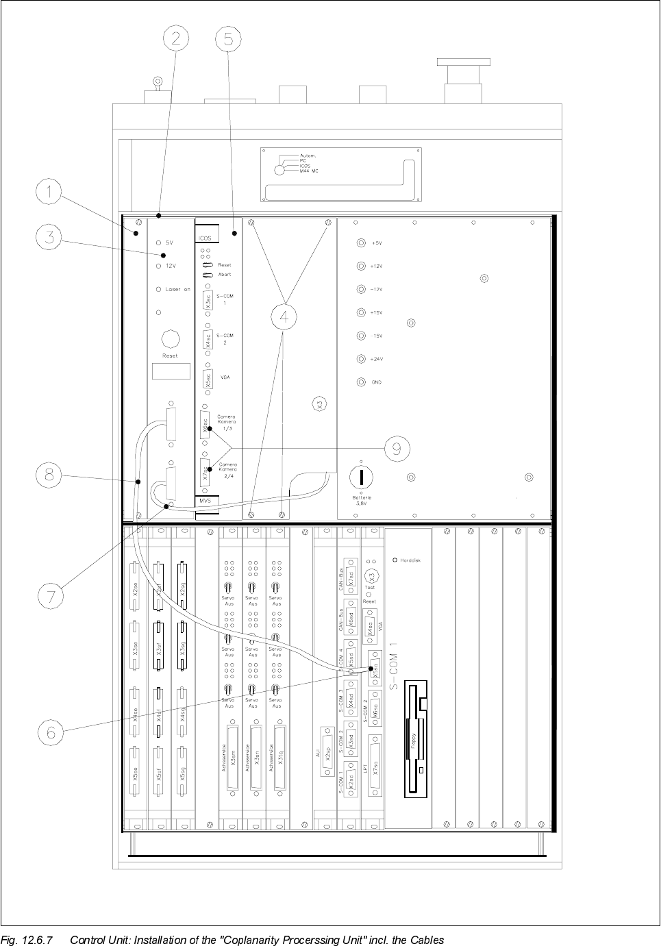
Key to Fig. 12.6.7 (look to your left):
1) Front subpanel, 2) 2 guide rails and 2 contact springs
Fasteners: 2 collar screws, slotted M2.5 x 11 per rail
3) Control unit : Coplanarity processing unit and 4) Fasteners for cover plate
15-pin connector X98 on back of control unit (4 Torx screws)
5) ICOS (on older control units the ICOS may also 6) Machine controller, COM 1
be located in the bottom row of plug-in slots ) (V 24 interface)
7) "Sensor cable coplanarity" 8) Cable: Coplanarity machine controller
9) These 2 connectors project over on the left
and must therefore be dismantled before
disassembly of coplanarity processing unit.
NOTE in re *)
for the Siemens service engineer:
For details about the cable "Coplanarity" (= cable harness X98 -> Power pack) -> Refer to: "Retrofitting
Instructions for Coplanarity Option", Item No. 00190 585-04.

12 Vision systems SIPLACE 80S-20/F4/F5 Service Manual
12.6 Coplanarity Option Edition 09/99
12 - 30
,QIRUPDWLRQDERXWWKH3URFHVV
DANGER O O O
During all work, comply with the Safety Instructions in Section 12.6.1.
- This chapter is valid for F4/F4-6/F5. Therefore references to "F5" have not been removed.
- Diese Anleitung ist für F4/F4-6/F5 gültig. "F4-6/F5" oder Angaben für SW V404.xx sind deshalb enthalten.
- It is time-consuming to dismantle the sensor bracket and the "sensor cable coplanarity" because this
requires the dismantling of the component table or the component changeover table, the cutter and - if
installed - the WPC.
2 people are required to dismantle the component table and the cutter.
There is a risk of being crushed and/or cut.
- Depending on the model of the SIPLACE 80 F4 machine involved, either the "old" cutter (with rotating
blade) or the "pneumatic cutter" (with stationary and movable cutting strips) is installed. Comply with the
appropriate service instructions during disassembly and assembly (Section 12.6.2).
- The sensor cable and the cable "Coplanarity - terminal panel" are only to be exchanged by the Sie-
mens service engtiineer or by service engineers of the customer’s whom Siemens has trained especially
for this task.
After the cable "Coplanarity - terminal panel" is exchanged, the safety circuit (laser shut-off) must
always be checked (see Section 12.6.15).
- All steps involving the cable (harness) "Coplanarity" must be performed only by the Siemens service
engineer (see NOTE under Fig. 12.6.3).
- In the case of SIPLACE machines with a dual conveyor (stationary side on left or right), 2 spacer washers
each of 1 mm thick is or must be installed on each screw fastening the sensor bracket.
- The flip-chip and IC camera remain installed during all service work. It is therefore not necessary to recali-
brate this camera.
- If the coplanarity sensor and/or the sensor retaining bracket is exchanged and re-installed, however, a cal-
ibration via SITEST is required (see Section 12.6.16).
- If a SIPLACE F4/F4-6/F5 machine still has the old model coplanarity option (= coplanarity laser module)
and it is faulty, it must always be exchanged for the new model (coplanarity option).
NOTE
Only the Siemens service engineer is permitted to carry out the conversion from "old" to "new".
NOTE for the Siemens service engineer: Refer to the "Retrofitting Instructions for Coplanarity Option
SIPLACE 80F4/(F4-6)/F5" available internally at Siemens in English and German, Item No. 00190 585-04.
It is contained in the retrofitting kit, Item No. 00117120-01.