80S-20贴片机.pdf - 第233页
SIPLACE 80 S-20/F4 Service Manual 7 Components Table Edition 03/97 7.6 Empty Tape Cutting Unit and Empty Tape Channel 7 - 31 ● Check wh ether the longi tudinal gu ide of the sl ide has b een mai ntained ( see Use r’ s Ma…

7 Components Table SIPLACE 80 S-20/F4 Service Manual
7.6 Empty Tape Cutting Unit and Empty Tape Channel Edition 03/97
7 - 30
7.6.2 Locating the Electrical Fault
NOTE
Error message No. 43 can point to a fault in the tape cutting unit or in the empty tape channel. Start fault loca-
tion by referring to the Section 7.2 ’Fault Characteristics’.
- In addition, in the section "Overview" under Section 7.1.3 ’Empty Tape Cutting Device’ you will find
information on the electrical and pneumatic systems as well as the functional sequence for evaluating
the fault situation.
- Use the circuit diagrams from the current circuit diagram folder. Details at to which diagram is needed
in each case will be found in the following text.
- In the course of fault location you will require the SITEST program for performing an individual cutting
stroke or starting continuous operation.
DANGER OOO
When the SITEST program is being used, particularly with the components changeover table removed (but
connected), there is increased risk of accidents at the tape cutting unit involving the cutter wheel and cutter
strip. When the test program is loaded do not reach into the area of the tape cutting unit, not even for fault cor-
rection or to connect up a multimeter, etc. Cordon off the area of the tape cutting unit correspondingly.
With all work, please read and observe in addition the DANGER note in the section "Fault characteristics"
7.6.2.1 Checking the + 30 V Electric Circuit : Fuse, Plug Connections,
Motor Activation, Solenoid Valve
● Select from within the track error menu "Abort placement" in order to return in the course of the following
reference run all of the components picked up at the placement heads.
● Check whether fuse F1 on the right-hand side of the connections panel of the communications unit has
interrupted the + 30 VDC electric circuit (see Fig. 7.5.1 and circuit diagram 1710460-Y0069-..-L.., Sh. 1).
● Fuse F1 is defective:
● Switch off the machine at the main switch.
● First correct the cause - such as, for example, a short circuit in the limit switch, in the cable Y637-W1/
W2, etc. (for fault location, see below) or in the tape feeder module - and then replace the fuse F1.
● Switch the machine back on and carry out a trial placement run with component pick-up from the tape
feeder modules of the previously faulty location.
● If no error message now occurs (the tapes are being cut), start the placement sequence.
● Fuse F1 is not defective:
● Load the SITEST program and start the cutting stroke by making the following selection:
"Component table" → "Single functions" → "Tape cutter". Check whether the cutting stroke is being
carried out, the pressure rod is swinging into position, the cutter wheel carriage returning to its parking
position on the left, the motor current being switched off and the pressure rod swinging away.
– The motor is being switched off after brief activation: there is stiffness in the performance of the cutting
stroke the + 30 VDC electric circuit has been interrupted by the PTC thermistor:

SIPLACE 80 S-20/F4 Service Manual 7 Components Table
Edition 03/97 7.6 Empty Tape Cutting Unit and Empty Tape Channel
7 - 31
● Check whether the longitudinal guide of the slide has been maintained (see User’s Manual, Sec-
tion 9).
● Check the pretensioning of the cutter wheel (see the section which follows).
● If necessary, correct the toothed belt tension of the cut and endless toothed belt
(see Section below).
– No motor activation, but the pressure rod swings into position (= solenoid valve switches):
● The motor is defective or there is an interruption between the motor and the plug X3ak at the tape
cutting unit
– No motor activation and the pressure rod does not swing into position (= solenoid valve is not switch-
ing):
● Check the plug connections, the limit switches and the cable Y637/Y638, as described below.
– Motor activation, but the pressure rod does not swing in:
● Check the wiring of the valve and compressed air circuit; if necessary, replace the solenoid valve.
– After the motor has switched out: pressure rod does not swing out: the solenoid valve is defective
(does not return to initial position).
7.6.2.2 Checking the Limit Switch and Cable Y637, Y638
● "Abort placement" has already been selected (see above).
DANGER QQQ
Switch off the machine at the main switch and disconnect it from the main power supply.
● Removing the components changeover table :
● Undo the plug connections of the components changeover table at the machine base on the right of
the components changeover table (mains plug and interface connector X37, and, if applicable, the
pneumatics connection).
● Open the protective covers and lift the cover at the components loading point upwards and out. Slide
the placement head by hand over the board conveyor. Please read the CAUTION note in Section 12.2
"Fault characteristics".
● Cut off the empty tapes - if they have not already been cut - at the front end of the module (= outside).
● Release the tape retainer and use a lift truck to lift and move the components changeover table
(including any feeder modules being used) carefully out of the machine as described in the User Man-
ual.
● The empty tape cutting unit remains installed in the machine for the following work.
CAUTION: OO
Do not reach into the area of the cutter strip and cutter wheel: danger of physical injury!
● Check the firm seating or good contact
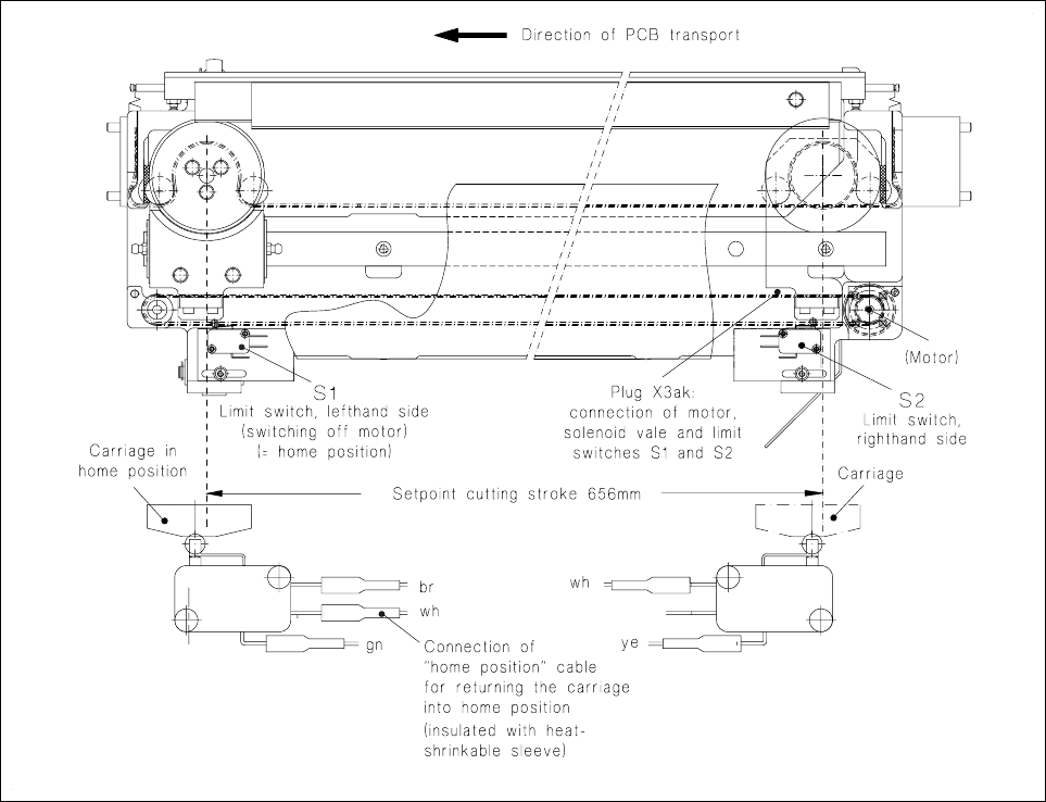
– of the plug connection X3ak (see Fig. 7.6.1) on the underside of the tape cutting unit,
– of the push-on receptacles at the d.c. motor (see Fig. 7.6.3),
– of the push-on receptacles at the limit switches S1 and S2 (see Fig. 7.6.1),
7 Components Table SIPLACE 80 S-20/F4 Service Manual
7.6 Empty Tape Cutting Unit and Empty Tape Channel Edition 03/97
7 - 32
● Check the limit switches S1 and S2 (see Fig. 7.6.1):
● Pull the push-on receptacles off the left-hand (S1) or right-hand (S2) limit switch and connect the ohm-
meter (acoustic signal with continuity) to the limit switch (see drawing 1710460-Y0637-..-L-..).
● Move the cutter wheel slide (caution: danger of injuring yourself on the cutter strip!) by hand into the
corresponding end position - left-hand or right-hand.
● If the limit switch does not respond, or if there is a short circuit, replace the limit switch as described in
Section 7.6.4 ’Replacing the Left-hand or Right-hand Limit Switch’.
Fig. 7.6.1 Checking the plug connection X3ak and the right-hand and left-hand limit switches
● Check the cables Y637-W1/W2 and Y638-(see circuit diagram 1710460-Y0637-..-L-.. and 1710460-
Y0638-..L..).:
– No break: continue with Section 7.6.9 ’D.C. Motor’.
– Cable break: replace the complete cable Y637 or cable Y638 as described in the next section. If there
is a defect in the resistor of the cable "Home position" Y638 also fit a new cable.